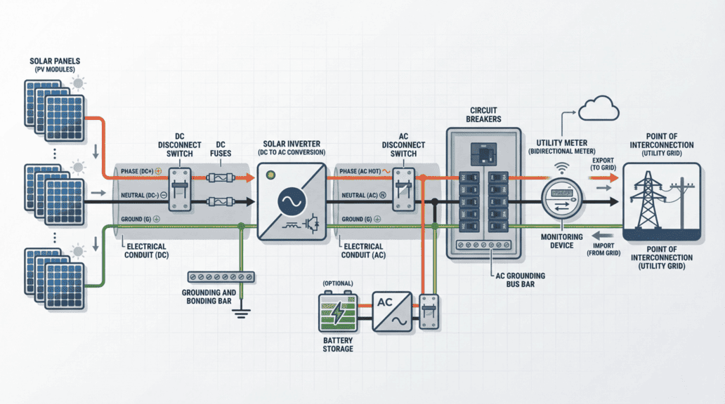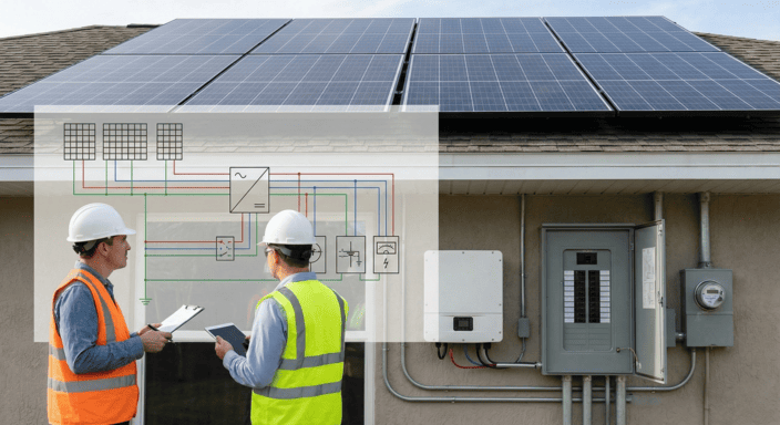

A solar three-line diagram is a detailed electrical schematic that shows every individual conductor, including phase (hot), neutral, and ground wires, in a photovoltaic system, unlike a one-line diagram which uses simplified single-line representations. Three-line diagrams are required by most authorities having jurisdiction (AHJs) for commercial solar installations, battery storage systems, and projects exceeding 25 kW capacity to verify National Electrical Code (NEC) compliance.
What is a Three-Line Diagram? Three-line diagrams (also called 3-line electrical diagrams) provide conductor-level detail essential for:
Solar permitting and inspections - AHJs require them to verify wire sizing, grounding, and overcurrent protection
Utility interconnection approval - utilities need to confirm safe grid connection and backfeed protection
Load calculations and code compliance - detailed conductor information ensures NEC Article 690 compliance
Troubleshooting and maintenance - shows exact wiring paths for all AC and DC circuits
Key components shown: Solar panels (PV modules), inverters, disconnect switches, breakers, fuses, grounding electrodes, equipment bonding, electrical conduit, wire sizing, meters, and point of interconnection (POI).
When required: Commercial systems, battery storage installations, systems over 25 kW, or whenever local AHJs mandate detailed electrical drawings beyond single-line diagrams.
Common software used: AutoCAD Electrical (industry standard), HelioScope (PV modeling), Solar Design Tool (NEC-compliant), SketchUp with electrical extensions, PV*SOL, and PVsyst.
For solar installers, mastering how to read and create a three-line diagram (or 3 line diagram electrical) is fundamental. While a single line diagram simplifies wiring, a three-line electrical diagram displays every conductor and connection, making it vital for solar permitting, inspections, and system troubleshooting.
A properly executed three-line diagram for solar guarantees your installation is safe, meets code requirements, and receives utility interconnection approval.

A solar three-line diagram is a detailed electrical schematic that illustrates power flow and conductor-level connections throughout a solar PV system. Rather than abstracting electrical paths like a one-line diagram does, a three-line diagram explicitly shows individual conductors, including phase (hot), neutral, and ground wires for every circuit. This comprehensive detail is necessary for precise load calculations, electrical code compliance, and proper system grounding and fault protection.
A properly designed three-line diagram incorporates several essential elements to guarantee safe and code-compliant installation:
Site Layout: A thorough plan for every structure and location where electrical components are positioned.
Solar Site Plan: Displays incoming utility services, substations, exterior transformers, feeders, trunk lines, and interconnection points between structures.
Symbols & Abbreviations: A standardized reference of electrical symbols and abbreviations utilized in the diagram.
Bill of Materials (BOM): An exhaustive inventory of electrical components, including conductors, disconnects, breakers, and inverters.
One-Line Diagram: A streamlined electrical diagram presenting the major components of the solar PV system and their interconnections.
A three-line diagram for solar charts the complete electrical configuration of a PV system, specifying how power travels through each component.
Essential elements of a solar three-line diagram include:
Solar panels (PV modules) – The electricity generation source.
Inverters – Transform DC electricity from panels into AC for residential or grid applications.
Disconnect switches – Critical for maintenance and emergency shutdowns and mandated for National Electrical Code compliance.
Breakers and fuses – Safeguard the system from overcurrent conditions.
Grounding and bonding – Guarantee electrical safety and system reliability.
Electrical conduit and wiring – Indicates conductor sizes, wire types, and routing paths.
Meters and monitoring devices – Display energy production and system performance.
Point of interconnection (POI) – The location where the system connects to the grid or main electrical panel.
Battery storage (if applicable) – Shows how energy storage integrates within the system.
These diagrams utilize three-line diagram symbols to represent components and connections with clarity. Comprehending these symbols is crucial for reading and producing professional system drawings.

Most authorities having jurisdiction (AHJs) demand a three line diagram electrical drawing as part of the solar permit application process. Unlike simplified layouts, a 3 line diagram displays the phase conductors, neutral, and ground paths for both AC and DC circuits. This comprehensive detail enables inspectors, electricians, and utility companies to confirm that the system satisfies the National Electrical Code (NEC), local amendments, and utility interconnection standards.
Providing a complete three line diagram guarantees:
Wiring verification – appropriate conductor sizing, phasing, and overcurrent protection.
Grounding and bonding compliance – AHJs verify that all grounding electrodes and equipment bonding are properly integrated.
Safe interconnection – utilities validate that backfeed circuits, disconnects, and main panel tie-ins won't jeopardize grid stability.
When planning a solar energy system, you'll encounter both one-line diagrams and three-line diagrams. Though they appear similar, they fulfill different purposes and provide varying levels of detail in system planning and permitting.
A one-line diagram is a simplified electrical drawing that presents the major components of a solar energy system, such as solar panels, inverters, disconnects, and utility connection, using single lines to represent electrical connections. It offers a high-level overview without displaying the individual wiring for each conductor.
A three-line diagram solar layout, conversely, builds upon this by detailing each individual conductor within the system. Rather than a single line for a connection, you'll observe three separate lines representing the hot (live), neutral, and ground wires. This comprehensive detail is frequently required for permitting, engineering reviews, and guaranteeing compliance with electrical codes.
Installers frequently wonder: When is a single line diagram sufficient, and when is a three line diagram necessary?
Here's the breakdown:
A three-line diagram solar layout may appear complicated initially, but once you analyze it, it becomes a valuable tool for understanding the solar system design, troubleshooting, and permitting. This type of solar energy diagram offers a detailed representation of electrical connections, displaying each individual conductor, including hot, neutral, and ground wires, rather than a simplified one-line view.
A standard three-line electrical diagram tracks the flow of electricity from the PV modules to the electrical panel, encompassing every key component throughout. Here's how to approach interpreting one:
Start at the Solar Panels
Identify the PV array on the diagram. Each module is depicted by its electrical output connections.
Search for the series and parallel configurations, which establish the total system voltage and current.
Track the DC wiring leading from the modules to the combiner box, if utilized.
Follow the DC Circuit
After the PV modules, find the DC disconnect switch. This safety device permits you to shut off power before it reaches the inverter.
Note the fuses or breakers incorporated for overcurrent protection.
Search for the polarity markings (+ and -) to verify correct wiring.
Locate the Inverter
The inverter transforms DC power from the solar panels into AC power for use in the electrical system.
Identify the input (DC side) and output (AC side) connections.
Some diagrams will feature multiple inverters or microinverters, each with its own wiring path.
Trace the AC Circuit
Following the inverter, electricity flows through an AC disconnect switch. This is mandated for safety and maintenance.
Next, search for breakers and fuses that protect the wiring before the electricity reaches the main electrical panel.
Track the electrical conduit and wiring to observe how the power is routed.
Identify AC vs. DC Circuits
DC circuits are typically designated with a solid line or a dashed line and will be labeled with voltage ratings like 600V DC or 1000V DC.
AC circuits are labeled with standard 208V, 240V, or 480V AC designations, depending on the system size.
Pay attention to the grounding and bonding connections, which guarantee safety and compliance with electrical codes.
Find the Point of Interconnection
The final step is where the solar system connects to the main electrical panel or utility grid.
This could be through a dedicated breaker in the panel, a subpanel, or a grid-tied metering system.
Search for monitoring devices that track power production and consumption.

A three-line diagram solar layout is a critical document for solar permitting and installation. Unlike a one-line diagram, a three-line electrical diagram for solar displays the actual wiring, including neutral and ground conductors, making it essential for guaranteeing compliance with the National Electrical Code (NEC) and utility requirements.
Producing an accurate three-line electrical diagram for solar demands the right tools. While some installers prefer drawing diagrams manually, most professionals utilize specialized software to guarantee precision. The drawback is that creating three-line diagrams for solar permits can be time-intensive.
Accurate solar three-line diagrams demand precise software that handles both electrical and photovoltaic system design. These programs are relied upon by solar engineers and electricians for producing AHJ-ready drawings and compliant permit plan sets.
AutoCAD Electrical – The industry benchmark for detailed electrical schematics, widely recognized by AHJs for solar permitting and engineering plan sets.
HelioScope – Outstanding for PV system modeling and layout, frequently combined with CAD software to generate comprehensive three-line diagrams.
Solar Design Tool – Delivers NEC-compliant diagrams with drag-and-drop functionality for residential and commercial PV systems.
SketchUp with Electrical Extensions – Excellent for visualizing conduit runs, junction boxes, and structural layouts in solar design.
PV*SOL & PVsyst – Primarily for performance modeling but can support diagram creation and inverter configuration.
Even seasoned solar installers commit errors when drafting or interpreting 3 line diagrams. Here are some of the most frequent issues that cause AHJ redlines or failed inspections:
Missing neutral connections – particularly in split-phase systems where neutral is necessary for load balancing.
Incorrect breaker sizing – undersized breakers can nuisance trip, oversized breakers violate NEC and create fire risks.
Forgetting equipment grounding conductors (EGCs) – inspectors frequently flag missing or mis-sized grounding wires.
Unclear or missing labels – AC/DC disconnects, rapid shutdown devices, and interconnection points must be labeled per NEC.
Improper conductor representation – not distinguishing between hot, neutral, and ground lines in the diagram.
Developing a compliant three-line electrical diagram for solar can be time-intensive, particularly for complex systems with multiple inverters or battery storage. A professional solar design service guarantees accuracy, NEC compliance, and faster solar permit approvals. This helps you prevent design errors, satisfy utility standards, and focus on installation.
A well-organized three-line diagram for solar should adhere to best practices to guarantee clarity and approval by AHJs (Authorities Having Jurisdiction) and utilities:
Incorporate symbols for solar panels, inverters, disconnect switches, breakers, fuses, grounding, conduit, and meters. Maintain consistency to prevent misinterpretation by inspectors and engineers. Utilizing industry-standard symbols guarantees clarity in communication, minimizes approval delays, and helps avoid installation errors that could result in safety hazards or system inefficiencies. Resources from organizations like the IEEE Power & Energy Society provide valuable guidance on electrical standards.
Specify voltage, current, conductor sizes, and circuit protection ratings in a solar three-line diagram. Display AC and DC circuit distinctions for easy identification. Clearly designate disconnect switches, grounding points, and interconnection locations to guarantee electricians, inspectors, and utility representatives can quickly comprehend the system layout and verify compliance. Understanding essential solar permit equipment requirements ensures all components are properly documented.
Guarantee proper grounding and bonding in compliance with NEC Article 690. Incorporate required rapid shutdown components as per NEC 690.12. Confirm wire sizing per NEC 310.15(B) to prevent overheating. Double-check voltage drop calculations to guarantee efficiency, particularly for long cable runs, as excessive voltage drop can diminish system performance and lead to compliance issues. The Union of Concerned Scientists offers insights into renewable energy safety standards.
Different utilities have unique interconnection standards, always reference the local interconnection agreement. Some may demand additional relays, meters, or disconnect switches beyond NEC requirements. Not satisfying these standards can result in project delays, additional costs, or system modifications after installation, so it's vital to review utility specifications early in the design process. State-specific guides like our California solar permit guide and Texas solar permits guide help navigate regional variations.

Understanding three-line diagrams is fundamental for designing safe, code-compliant solar installations. Whether you're new to the industry or refining your skills, mastering these diagrams helps you troubleshoot issues, streamline permitting, and communicate effectively with inspectors and utilities.
To sharpen your skills, explore NEC guidelines, use professional design software, and review real-world diagrams. When scaling your business or managing an influx of projects, Solar Permit Solutions offers professional solar design and permitting support that can be invaluable. Organizations like SolSmart provide excellent resources for solar professionals looking to enhance their technical capabilities.
With proper training and the right resources, you can navigate complex permitting processes by delivering precise, code-compliant three-line diagrams. Access to licensed professional engineers (PEs) who can provide solar engineering stamps for jurisdictions that require them ensures your plans meet all AHJ and utility requirements. Whether you're working on grid-tied systems or exploring off-grid solar system design, understanding three-line diagrams is crucial for success.
Whether you need to speed up approvals, improve accuracy, or handle higher project volumes, mastering three-line diagrams is essential for reliable solar design and installation success. Global organizations like the Center for Climate and Energy Solutions and REN21 provide valuable data on renewable energy trends and best practices.
Mastering three-line diagrams is a non-negotiable skill for any solar professional looking to deliver quality installations and navigate the permitting process successfully. These detailed electrical schematics serve as the blueprint for safe, code-compliant solar systems, providing the level of transparency that inspectors, utilities, and AHJs require to approve your projects.
While creating accurate three-line diagrams demands time, attention to detail, and knowledge of NEC standards, the investment pays dividends through faster permit approvals, fewer installation errors, and reduced risk of costly corrections. Whether you're working on a small residential solar design or a complex commercial installation with battery storage, understanding how to read, interpret, and create these diagrams will set you apart as a competent professional in the solar industry.
As solar technology continues to evolve and electrical codes become more stringent, staying current with best practices for three-line diagram creation remains essential. Leverage the right software tools, continually reference NEC guidelines, and don't hesitate to contact our team when tackling complex systems. Resources from the World Bank Energy Sector, UNEP Energy Program, and ENERGY STAR can provide additional context on global energy efficiency standards. Your commitment to producing clear, accurate three-line diagrams directly translates to safer installations, satisfied customers, and a stronger reputation in the competitive solar marketplace.
For comprehensive guidance on navigating various jurisdictional requirements, explore our comprehensive solar permit guide. Additionally, understanding solar radiation patterns and accessing climate data from NOAA can enhance your system design accuracy. Visit our blog for more resources on solar design and permitting best practices.
What's the main difference between a one-line diagram and a three-line diagram in solar installations?
A one-line diagram provides a simplified overview of a solar system, using single lines to represent electrical connections between major components like panels, inverters, and disconnects. In contrast, a three-line diagram shows each individual conductor, including hot, neutral, and ground wires, for every circuit in the system. Three-line diagrams are more detailed and are typically required for commercial installations, systems with battery storage, or whenever AHJs need comprehensive information to verify wire sizing, grounding, and protection devices meet code requirements.
Do all solar installations require a three-line diagram for permitting?
Not all solar installations require a three-line diagram. Smaller residential systems (typically under 25 kW) can often be permitted with just a one-line or single-line diagram. However, larger commercial systems, installations with battery storage, or projects in jurisdictions with strict requirements will need three-line diagrams. Requirements vary by AHJ and utility company, so always check local permitting guidelines before starting your design. When in doubt, contact your local building department to confirm what level of detail they require.
What are the most common mistakes installers make when creating three-line diagrams?
The most frequent errors include missing neutral connections in split-phase systems, incorrect breaker sizing that either causes nuisance tripping or violates NEC safety standards, and forgetting to include or properly size equipment grounding conductors (EGCs). Additionally, many installers fail to clearly label AC/DC disconnects, rapid shutdown devices, and interconnection points as required by NEC. Improper conductor representation, not clearly distinguishing between hot, neutral, and ground lines, is another common issue that leads to inspector redlines and failed inspections.
What software is best for creating professional three-line diagrams?
AutoCAD Electrical remains the industry standard and is widely accepted by AHJs for solar permitting due to its precision and professional output. HelioScope excels at PV system modeling and is often paired with CAD software for complete diagrams. Solar Design Tool offers NEC-compliant diagrams with user-friendly drag-and-drop functionality, making it ideal for installers who want efficiency without sacrificing accuracy. SketchUp with electrical extensions is excellent for visualizing physical layouts, while PV*SOL and PVsyst primarily handle performance modeling but can assist with diagram generation. Your choice should depend on project complexity, budget, and AHJ preferences in your area.
How do I ensure my three-line diagram meets both NEC and utility interconnection requirements?
Start by thoroughly reviewing NEC Article 690 for solar-specific requirements, including proper grounding, bonding, and rapid shutdown components per NEC 690.12. Verify all wire sizing follows NEC 310.15(B) and calculate voltage drops for long cable runs. Next, obtain and study your local utility's interconnection agreement, as they often have additional requirements beyond the NEC, such as specific relay configurations, metering equipment, or disconnect switch placement. Contact the utility's interconnection department early in your design process to clarify their expectations. Including all required symbols, labels, and component ratings clearly on your diagram will help ensure smooth approval from both electrical inspectors and utility reviewers.
We are dedicated to providing top-notch solar permit services to homeowners, business owners, DIY, and solar installers. Contact us today.