Proper wire sizing for solar PV systems requires selecting conductors based on three critical factors: ampacity rating, voltage drop percentage, and wire run length. The American Wire Gauge (AWG) system determines wire capacity, where lower gauge numbers (such as 10 AWG, 6 AWG, or 1/0 AWG) indicate larger wire diameters capable of safely carrying higher current.
Solar system wire sizing directly impacts system performance and safety. Undersized wiring causes voltage drop exceeding 2%, resulting in power loss and reduced efficiency. Additionally, conductors carrying current beyond their ampacity rating create fire hazards from excessive heat buildup.
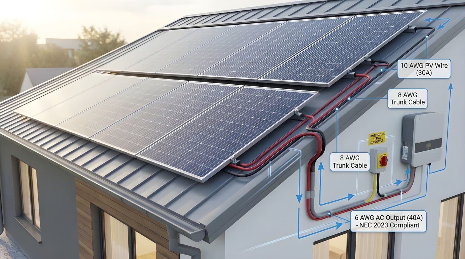
Wire gauge selection varies by location within the solar system. Panel-to-combiner connections typically use 10 AWG wire (30 amp capacity). Combiner-to-charge controller wiring often requires 6 or 8 AWG (55 to 40 amps). Battery bank connections demand the largest conductors, frequently 1/0 AWG or larger, due to high DC current requirements from power inverters.
System voltage significantly affects wire size requirements. A 12V system carrying 25 amps with 10 AWG wire supports only 4.5 feet of cable run while maintaining 2% voltage drop. Doubling system voltage to 24V doubles the allowable wire length. Upgrading to 4 AWG wire extends the run to 18 feet at the same voltage and current.
Electrical conductors function like water hoses. Larger diameter wires have lower resistance, allowing more current to flow safely. Longer wire runs increase resistance, reducing delivered power to battery banks or the electrical grid. The AWG scale measures copper conductors, with lower numbers indicating reduced resistance and higher current carrying capacity.
The following chart displays various wire gauge sizes with their typical amp ratings and applications for both residential and solar installations.

Standard Residential Applications (Wire Gauge and Capacity)
The residential section displays American Wire Gauge (AWG) standards with typical applications and ampacity (current carrying capacity):

Solar PV Applications (System Components and Wire Designation)
The solar section illustrates typical off-grid solar systems or grid-tied installations with wire designations (A, B, C, D) corresponding to appropriate gauge for current flow at each connection point:
Solar Panels to Combiners
C (Green Arrows): Wiring between solar panels and combiner boxes carries array current. Applications typically utilize 10 Gauge wire (30 Amps), though sizing calculations are based on maximum string current and panel specifications.
Combiners to Charge Controller/GTI
B (Blue Arrows): Wiring from combiner boxes to Charge Controllers or Grid-Tie Inverters (GTI) carries total array current. Sizing ranges from 6 to 8 Gauge (55 or 40 Amps), depending on total power output.
Charge Controller to Battery Bank
B (Blue Arrow):* Wiring from Charge Controllers to Battery Banks typically carries high current, potentially requiring 6 or 8 Gauge (55 or 40 Amps).
Battery Bank to Power Inverter
A (Red Line): Wiring from Battery Banks to Power Inverters often carries the highest DC current in systems (especially at 12V or 24V) and frequently requires large gauge wire such as 3/0, 1/0, or 3 Gauge (200, 150, or 100 Amps).
GTI to Grid / Power Inverter to AC Devices
D (Orange Arrows): AC output wiring includes:
- GTI to Grid connections
- Power Inverter to AC Device connections
- AC wiring typically uses 14 Gauge (15 Amps) for small loads or higher gauges based on inverter AC output ratings
Commercial solar PV panels rated over 50 watts typically utilize 10 gauge (AWG) wires, accommodating up to 30 amps of current flow from a single panel. When combining multiple panels in parallel configurations, three to eight AWG “combiner” wire sets are generally required to safely transfer power to charge controllers or GTIs, following solar standards.
Wiring from charge controllers to battery banks can generally match or exceed the main gauge from PV arrays. The exception (B*) occurs when Charge Controllers operate 12 or 24-volt battery banks while PV arrays operate at higher voltages, such as 48 Vdc and above. These Charge Controllers contain large transformers that reduce voltage while increasing current to battery banks. Installation materials for specific charge controllers should be consulted when selecting correct wire sizing.
Wiring between batteries in battery banks tends to be the largest in systems, as these conductors work in conjunction with power inverters that can demand more current than PV systems can supply independently. These same wires must also carry current used simultaneously for charging and power inversion. Typical battery bank wire size is 1/0 or “one-ought.”
Matching gauge and wire lengths when combining batteries in battery banks is critically important. Failure to do so can shorten battery bank lifespan and create safety hazards.

Wire Run Lengths
The longest wire run typically extends from PV arrays to charge controller or GTI locations. Since all combined PV power flows through this wire set, proper selection is essential to maximize performance and ensure safety.
The standard guideline maintains voltage drop below 2% on this run. Using known resistance values of various wire gauges, maximum length for wire pairs can be calculated for each gauge size.
The following calculation applies to 12V PV systems. Wire lengths can be doubled for 24V systems or quadrupled for 48V systems.
2% Voltage Drop Chart
Practical Example
Consider a 450-watt 12V system. At the Vmp of 18V, maximum current equals 450/18 = 25 amps.
Examining the wire capacity row, 10 AWG represents the smallest gauge wire that can be safely used, rated at 30 amps, exceeding the required 25 amps.
Next, reviewing the Array amps column at row “25” reveals that a 10 AWG wire pair only supports a cable length of 4.5 feet. Upgrading to 4 AWG supports up to 18 feet while remaining within the 2% loss criteria. These distances are quite limited.
This example demonstrates the critical importance of cable length and its effect on power losses. Many installations feature long cable runs without recognizing the performance impact. Sometimes tolerating a 4% loss rather than 2% becomes necessary, allowing doubled length values from the table. Another option involves operating at higher voltages, such as 24V, which reduces amperage and wire losses.
The objective is to design systems using safe wire sizing while remaining conscious of tradeoffs between system voltage, wire length, line losses, and costs. Detailed planning should be completed before purchasing components like cables.
Solar Permit Solutions
Need Solar Permit Plans?
Professional, permit-ready solar plan sets delivered fast. Residential and commercial projects across all 50 states.
Conclusion
Proper wire sizing represents a fundamental aspect of solar system design that directly impacts both safety and performance. Understanding the relationship between wire gauge, current capacity, and voltage drop enables system designers to make informed decisions that optimize energy delivery while maintaining safe operating conditions.
The principles outlined in this guide demonstrate that wire selection extends beyond simply meeting ampacity requirements. Cable run distances, system voltage, and acceptable power loss thresholds all play critical roles in determining appropriate conductor sizing. While it may be tempting to minimize costs by selecting smaller gauge wires, the long-term consequences of inadequate wiring include reduced system efficiency, potential fire hazards, and compromised equipment performance.
Successful solar installations require careful attention to wire specifications at every connection point, from individual panel strings through combiner boxes, charge controllers, battery banks, and inverters. By applying the 2% voltage drop guideline and consulting ampacity charts, system designers can ensure that electrical infrastructure supports optimal power transfer throughout the installation’s lifespan.
Taking time to properly calculate wire requirements before purchasing materials prevents costly mistakes and ensures that solar systems deliver maximum performance and safety for years to come. Professional solar design services can help verify proper wire sizing and ensure compliance with electrical code requirements.
FAQs
Need help with your solar installation? Contact us for professional guidance on wire sizing and solar permitting requirements. Our team specializes in residential and commercial solar projects, ensuring your system meets all permit requirements and safety standards. Review our blog for more solar installation guides, including state-specific regulations, California requirements, and equipment specifications. Learn how to avoid common permit mistakes and streamline processing with our comprehensive resources on nationwide permit standards, permitting guidelines, and code compliance.


