
Solar structural design calculations evaluate whether a roof or ground-mount structure can safely support a photovoltaic system by analyzing dead loads (2–4 psf for panels and racking), live loads, wind uplift per ASCE 7-22, snow accumulation, and seismic forces – then comparing combined loads against the structure’s rated capacity with IBC-required safety factors.
The process ensures solar installations withstand environmental conditions while maintaining optimal energy production angles.
What Are Solar Structure Design Calculations?
Solar structure design calculations are the technical process engineers use to specify requirements for solar mounting systems. The calculations determine three primary factors: structural strength (load-bearing capacity), dimensional sizing (beam, rail, and column specifications), and optimal positioning (tilt angle and orientation based on latitude). Engineers follow building codes such as ASCE 7 and IS 875 to calculate how structures will perform under combined loading scenarios including wind speeds up to design limits, snow accumulation, and seismic activity.
The calculation process involves seven sequential steps: site evaluation (collecting location data and soil properties), load calculation (quantifying all force types), structural member sizing (determining component dimensions), tilt and orientation optimization (setting panel angles), foundation calculation (designing anchoring systems), structural analysis (testing under simulated loads), and compliance verification (ensuring code adherence with safety factors of 1.5 to 2.0).
Accurate calculations prevent structural failures, extend system lifespan beyond 25 years, maximize energy efficiency through proper 10-degree seasonal tilt adjustments, balance costs by avoiding overdesign, and satisfy regulatory requirements. Material selection between galvanized steel, aluminum alloys, and stainless steel depends on corrosion resistance needs, while foundation types (concrete, ballast, or pile-driven) are determined by soil bearing capacity and wind load requirements.
Why Every Solar Project Needs Structural Analysis
Safety: Flawed calculations can lead to structural collapses that result in accidents or property damage.
Longevity: Accurate computations ensure the system withstands environmental pressures for decades.
Energy Optimization: Correct tilt and orientation maximize solar panel efficiency.
Economic Balance: Overdesigning increases costs unnecessarily, while underdesigning creates failure risks. Proper calculations ensure affordability.
Regulatory Adherence: Comprehensive structural design calculations are often mandated by engineering codes and renewable energy regulations.
Structural analysis is not optional paperwork. It is a safety requirement embedded in building codes and enforced by local permitting offices. The International Building Code (IBC) and International Residential Code (IRC) both require construction documents to clearly indicate dead loads for panels, support systems, and ballast. Roof structures must also demonstrate capacity for applicable live loads even with solar panels present.
Beyond code compliance, structural analysis protects contractors from liability. An installation that overloads a roof can cause sagging, water damage, or in extreme cases, partial collapse. Ground-mount foundations that fail to account for frost heave or lateral wind forces can shift over time, compromising panel alignment and electrical connections. These failures create financial exposure for the installing company and can result in insurance claims, warranty disputes, and reputational damage.
Structural calculations also drive project economics. When an engineer identifies limited remaining roof capacity, the design team can adjust module placement, reduce array size, or recommend reinforcement before construction begins. This proactive approach prevents the significantly more expensive scenario of discovering structural problems during or after installation.

Critical Components In Solar Structure Design Calculations
- Load Calculations
Load calculation stands as one of the most vital aspects of solar structure design. Every solar mounting system must support multiple load categories, including seismic, wind, snow, dead, and live loads. Dead load encompasses the weight of solar panels, modules, and mounting hardware. Live load accounts for temporary forces such as workers, equipment, or maintenance activities. Wind load proves particularly critical in high wind velocity regions, as it generates uplift and drag forces on panels. Snow load applies in colder climates where snow accumulation adds substantial weight. In earthquake-prone areas, seismic load becomes significant, with both vertical and horizontal forces potentially affecting stability. Accurate calculation of these loads ensures the solar structure remains strong enough to handle environmental conditions without excessive overengineering that drives up costs.
The Four Load Types in Solar Structural Design
Structural engineers evaluate four primary load categories when analyzing a solar installation. Each load type contributes to the total demand on the structure, and all four must be accounted for in the combined load calculations required by ASCE 7-22 and the IBC.
Dead Load: The Permanent Weight of the System
Dead load is the static, permanent weight added by the solar installation. This includes every component that remains on the structure for the life of the system: photovoltaic modules (typically 40 to 50 pounds each for residential panels), mounting rails and clamps, flashing and hardware, microinverters or power optimizers (if panel-level), and conduit and wiring.
When distributed across the array footprint, most residential rooftop systems add 2 to 4 pounds per square foot (psf) of dead load. However, this weight is not truly distributed evenly. Mounting brackets create concentrated point loads at each rafter attachment, which means the actual force on individual structural members can be significantly higher than the average distributed figure. For example, attaching to every other rafter effectively doubles the load on those specific members compared to attaching at every rafter location.
For ballasted flat-roof systems, dead load increases substantially because concrete blocks or pavers are added to resist wind uplift without roof penetrations. Ballasted systems can add 5 to 15 psf or more depending on wind zone and system height above the roof surface. ASCE 7-22 classifies the weight of solar panels, their support system, and ballast as dead load for all load combination calculations.
Live Load: Temporary and Variable Forces
Live loads are temporary forces the roof must support in addition to its permanent dead load. For solar installations, the most significant live load considerations are maintenance access (calculated at 20 psf per code for roof areas accessible to workers) and snow accumulation in applicable climate zones.
ASCE 7-22 introduced specific provisions for how live loads interact with solar arrays. If any portion of the solar system rises more than 24 inches above the roof surface, engineers must model live load in that area of the system. If the entire system sits within 24 inches of a low-slope roof, live load modeling under the panels may not be required, although the uncovered portions of the roof still require uniform live load analysis. A 300-pound concentrated load must also be calculated for all roof surfaces subject to maintenance access.
Snow load varies dramatically by geographic location and is determined using ground snow load data from ASCE 7-22, adjusted for roof slope, exposure category, and thermal conditions. In northern states, snow accumulation around and between panels can create concentrated loads that exceed the uniform ground snow load assumption. Engineers must also account for snow drifting against raised panel edges, particularly on low-slope commercial roofs.
Wind Load: Uplift and Downward Pressure
Wind load is typically the most complex and consequential calculation in solar structural design. Wind creates both downward pressure and upward lift on solar panels, and the forces vary based on a panel’s position within the array, its proximity to roof edges and ridges, the building’s height and exposure category, and the basic wind speed for the project location.
ASCE 7-22 provides the current framework for calculating wind loads on rooftop solar installations. The standard introduced dedicated pressure coefficients specifically developed for solar arrays through extensive wind tunnel testing, replacing the inconsistent approaches engineers previously relied on. The wind pressure formula consists of four components: velocity pressure, external pressure coefficients, an edge factor (γE) of 1.5 for exposed panels or 1.0 for interior panels, and an equalization factor (γA) ranging from 0.4 to 0.8 based on effective wind area.
For ground-mounted systems, ASCE 7-22 Section 29.4.5 provides specific provisions that were not present in earlier code editions. Ground-mount wind load calculations must account for tilt angle, ground clearance, terrain roughness, and array configuration. Panels tilted at angles exceeding 45 degrees are treated as solid signs rather than open-building monoslope roofs, which changes the applicable pressure coefficients.
Wind uplift forces can be powerful enough to detach panels from a roof if the racking system is not adequately anchored. In high-wind zones, including hurricane-prone coastal regions, attachment point counts increase and may require reinforced connection methods. The attachment spacing, fastener type, and pullout resistance of each connection point must all be verified against the calculated wind uplift demand.
Seismic Load: Lateral Force Resistance
Seismic analysis for solar installations extends well beyond California. ASCE 7-22 Section 13.3 treats solar arrays as nonstructural components requiring seismic design across much of the United States. The weight of the solar system directly impacts seismic calculations because lateral forces during an earthquake are proportional to the mass of the attached components.
Engineers evaluate how the added mass of the solar array will respond to ground motion, ensuring the racking and its attachments can resist lateral forces without detaching or causing structural damage to the building. Mounting systems must be interconnected and capable of distributing lateral forces without deforming. These criteria discourage irregular array shapes that cannot distribute seismic forces effectively.
For ballasted systems on low-slope roofs, ASCE 7-22 Section 13.6.12 establishes seven specific conditions for seismic compliance, including maximum expected displacement calculations. The displacement can be determined through the formula provided in the standard, shake table testing, nonlinear response history analysis, or any method acceptable to the building official.
- Panel Tilt Angle And Orientation
The tilt angle and orientation of solar panels directly influence energy production in a solar power system. Tilt angle is typically determined based on the installation location’s latitude to achieve optimal solar exposure year-round. Generally, the tilt angle should match the latitude, with minor seasonal adjustments achieved by adding 10 degrees in winter and subtracting 10 degrees in summer. Orientation refers to the compass direction panels face. For maximum performance, solar panels should face true south in the Northern Hemisphere and true north in the Southern Hemisphere. This component is critical in solar design because incorrect tilt and orientation can cause significant energy losses.
- Material Selection
Choosing appropriate materials is crucial for creating solar structures that are both durable and cost effective. Most solar mounting systems utilize galvanized steel, aluminum alloys, or stainless steel. Galvanized steel is ideal for long-term outdoor installations due to its strength and corrosion resistance. Aluminum suits both rooftop and ground-mounted systems as it is lightweight, manageable, and rust-resistant. While more expensive, stainless steel provides exceptional durability in high-humidity environments or coastal areas where corrosion poses a major concern. The mechanical properties of materials, including yield strength, tensile strength, and environmental stress resistance, are carefully evaluated during solar structural calculations to ensure system longevity and reliability.
- Foundation Design
Foundation design serves as the cornerstone of any ground-mounted solar installation. Soil conditions, wind loads, and total system weight all influence foundation requirements. Foundations must anchor the solar system to prevent toppling or shifting under external forces. Common foundation types include concrete foundations for permanent ground-mount systems, ballast foundations for rooftops where penetration is prohibited, and pile-driven foundations for utility-scale solar farms. In colder climates, frost depth and soil bearing capacity determine the foundation’s depth and dimensions. Without proper foundation calculations, even perfectly designed mounting structures can fail, making this a critical consideration during the design phase.
- Structural Stability
Structural stability results from precise design calculations and appropriate material selections. It ensures the solar mounting system remains secure and functional for decades, even when subjected to dynamic forces like wind, snow, and seismic activity. A stability check verifies that deflections, stresses, and moments in structural members stay within permissible limits. Engineers incorporate safety factors, typically ranging from 1.5 to 2.0, to account for unforeseen circumstances and uncertainties. Structural stability matters for both safety and maintaining optimal panel positioning, as even minor misalignments can reduce energy generation. This element guarantees the solar installation’s reliability and long-term performance.
Solar Permit Solutions
Need Solar Permit Plans?
Professional, permit-ready solar plan sets delivered fast. Residential and commercial projects across all 50 states.
Roof-Mount vs. Ground-Mount: How Structural Calculations Differ
While the same four load types apply to both roof-mounted and ground-mounted solar installations, the structural calculation process differs significantly between the two configurations.
Roof-Mount Structural Calculations
Roof-mount calculations focus on the existing structure’s capacity to accept additional load. The engineer must determine the original design loads for the roof framing, verify the current condition of structural members, calculate the additional demand from the solar system, and confirm that combined loads remain within the structure’s rated capacity with appropriate safety factors.
This process requires access to original building plans (when available), knowledge of local building codes at the time of construction, and often a physical site survey to verify rafter or truss dimensions, spacing, material grade, and condition. For wood-framed residential roofs, engineers reference IRC span tables and lumber grading assumptions that vary by geographic region. Rafter sag measured in inches should not exceed the span measured in feet divided by 20, which corresponds to a dead load deflection limit of span/240.
Point load analysis is especially important for roof mounts. Each attachment point transfers the weight of the panels and racking plus environmental loads into a specific location on a rafter or truss chord. The engineer must verify that the member can handle this concentrated force without exceeding its bending or shear capacity. Attachment spacing, lag screw embedment depth, and pullout resistance testing (when required) all factor into this analysis.
Ground-Mount Structural Calculations
Ground-mount structural calculations shift the focus from an existing structure to a purpose-built foundation and racking system. Engineers must analyze soil bearing capacity to determine foundation type (driven piles, helical piers, or concrete footings), frost depth to establish minimum foundation embedment, wind load on the full exposed array using ASCE 7-22 Section 29.4.5, and overturning moment at the base of each support post.
Soil conditions introduce variables that do not exist in roof-mount calculations. A geotechnical report or soil classification may be required to determine bearing capacity, lateral resistance of embedded piles, and potential for frost heave. In expansive clay soils, foundation design must account for seasonal volume changes that can shift post positions and compromise panel alignment.
Ground-mount systems also require consideration of clearance height, row spacing, and tilt angle optimization. Higher tilt angles increase wind exposure and overturning forces but improve energy production in northern latitudes. The structural engineer must balance these competing demands within the constraints of the site’s wind speed, snow load, and seismic zone designations.

Step-By-Step Solar Structure Design Calculation Process
Step 1: Gather Existing Structural Data.
The design process begins with a site assessment to gather essential data including location coordinates, wind speed, seismic activity, and soil properties.
For roof mounts, this means obtaining original building plans (if available), measuring rafter or truss dimensions and spacing, identifying lumber species and grade, assessing roof age and visible condition, and documenting the existing roofing material and its weight. For ground mounts, site survey data, soil classification, and topographic information are collected.
Step 2: Determine Site-Specific Environmental Loads.
Using the project’s geographic coordinates, the engineer identifies the applicable basic wind speed, ground snow load, seismic design category, and exposure category from maps and tables. These values vary significantly across the country and even within individual states. Standards such as IS 875 or ASCE 7 ensure accuracy and safety.
Step 3: Quantify the Solar System Load.
The engineer totals all component weights for dead load calculations, including modules (from manufacturer spec sheets), racking and mounting hardware, fasteners and flashing, microinverters or optimizers (if applicable), conduit and wiring, and ballast (for non-penetrating systems). The total weight is then distributed to determine both average psf loading and concentrated point loads at each attachment.
Step 4: Calculate Combined Loads Using ASCE 7-22 Combinations.
Each applicable load combination is evaluated to determine the maximum demand on every structural member and connection. The controlling combination (the one that produces the highest demand-to-capacity ratio) drives the design.
ASCE 7-22 Load Combinations for Solar Structural Design
Structural engineers do not evaluate loads in isolation. Building codes require specific load combinations that represent realistic worst-case scenarios. ASCE 7-22 defines multiple load combinations, and the structure must demonstrate adequate capacity under each applicable combination. The most relevant combinations for solar projects include:
|
Combination |
Components | Primary Check |
|
1.4D |
Dead load only (gravity check) |
Self-weight verification |
|
1.2D + 1.6L + 0.5(Lr or S) |
Dead + live + roof live or snow |
General gravity loading |
|
1.2D + 1.0W + L + 0.5(Lr or S) |
Dead + wind + live + roof live or snow |
Wind-dominant scenario |
|
1.2D + 1.0E + L + 0.2S |
Dead + earthquake + live + snow |
Seismic-dominant scenario |
|
0.9D + 1.0W |
Dead + wind (net uplift check) |
Wind uplift critical check |
| 0.9D + 1.0E | Dead + earthquake |
Seismic uplift/overturn |
The 0.9D + 1.0W combination is particularly critical for rooftop solar because it checks net uplift: can the wind literally pull the panels and racking off the roof? When wind uplift exceeds 90% of the dead load holding the system down, the attachment design becomes the controlling factor. This is why wind uplift calculations drive attachment spacing and fastener selection for most installations.
Step 5: Tilt And Orientation
Panels are angled according to the location’s latitude, with adjustments made for seasonal efficiency. Orientation is set to face either true south in the Northern Hemisphere or true north in the Southern Hemisphere to optimize solar exposure.
Step 6: Foundation Calculation
The foundation is designed to securely anchor the structure against seismic and wind forces. Its depth and type, such as pile-driven, concrete, or ballast, are determined based on soil bearing capacity and installation requirements.
Step 7: Structural Analysis
Before finalization, the system undergoes structural analysis using software tools to test it under simulated loads. This confirms stresses, deflections, and stability, helping ensure the design meets performance standards.
The combined load demand must remain within the structure’s rated capacity, typically with a safety factor reflected in the load combination factors. If any member or connection exceeds its capacity under any load combination, the engineer must recommend modifications: reducing array size, repositioning panels away from overstressed areas, adding structural reinforcement, or changing the racking system to one with lighter weight or wider attachment spacing.
Step 8: Safety And Compliance Review
Finally, the design is reviewed for conformity with relevant engineering codes, and safety factors are applied to address uncertainties. This phase ensures long-term durability, safety, and regulatory approval.
When PE-Stamped Structural Calculations Are Required
Professional Engineer (PE) stamp requirements for solar structural calculations vary by jurisdiction, but most AHJs in the United States require them for at least some project types. The PE stamp signifies that a licensed engineer has reviewed the design, performed or verified the calculations, and takes professional responsibility for their accuracy.
Common triggers for PE-stamped structural calculations include systems exceeding a threshold size (often 10 to 25 kW depending on the jurisdiction), installations on structures built before a specific year (commonly pre-1970 or pre-1980 construction), ground-mounted arrays (almost universally require PE stamps), commercial and multifamily buildings, and projects in high-wind zones, high-snow-load areas, or seismic design categories D through F.
Some jurisdictions have adopted simplified permitting pathways for qualifying residential systems. California’s SolarAPP+ program, for example, uses a prescriptive structural checklist that allows eligible systems to bypass traditional PE-stamped calculations. Similarly, the SolSmart program has developed standardized structural checklists based on the SEAOC/ICC structural criteria. These simplified pathways reduce cost and timeline for straightforward residential installations while maintaining safety through prescriptive requirements.
Even when a PE stamp is not explicitly required, having structural calculations prepared by a qualified professional reduces rejection rates at plan review and provides liability protection for the installing contractor. Many experienced solar companies include structural engineering review as a standard part of their project workflow regardless of local requirements.
Common Structural Design Mistakes That Delay Solar Permits
Permit reviewers at AHJs across the country see the same structural calculation errors repeatedly. Avoiding these common mistakes can significantly reduce rejection rates and revision cycles.
Using outdated code references. Submitting calculations based on ASCE 7-10 when the local jurisdiction has adopted ASCE 7-16 or ASCE 7-22 is one of the most frequent causes of plan review rejection. The wind load provisions changed substantially between editions, and using older pressure coefficients produces inaccurate results. Always verify which edition of ASCE 7 the local building code references before beginning calculations.
Treating dead load as uniformly distributed. Solar panel weight is often expressed as 2 to 4 psf distributed load, but the actual forces on individual structural members depend on attachment spacing and point load distribution. Engineers must calculate the concentrated load at each attachment point and verify that the receiving member can handle it, not just check the average distributed load against the roof’s rated capacity.
Ignoring wind uplift on edge and corner panels. ASCE 7-22 assigns significantly higher pressure coefficients to panels near roof edges and corners compared to interior panels. An array layout that places panels in roof edge zones without accounting for the increased wind uplift demand will fail plan review. Design tools from racking manufacturers like IronRidge and Unirac incorporate roof zone mapping, but the engineer must verify that the zone boundaries are correctly defined for the specific building.
Missing the snow drift analysis. In snow load regions, panels can create drift conditions where snow accumulates against the uphill edge of a tilted array. This concentrated snow load can exceed the uniform roof snow load assumption and overload the members directly beneath the drift zone. This is particularly common on low-slope commercial roofs where rows of panels create multiple potential drift locations.
Omitting seismic calculations outside of California. Many designers associate seismic requirements exclusively with California and the Pacific Northwest, but ASCE 7-22 requires seismic design for solar arrays in seismic design categories C through F, which includes large portions of the central and eastern United States. Projects in states like Tennessee, South Carolina, Missouri, and Arkansas often require seismic analysis that designers unfamiliar with the region’s seismicity may overlook.
Failing to verify existing roof condition. Calculations based on original design capacity assume the roof has not deteriorated since construction. Water damage, insect damage, rot in wood members, or prior modifications can reduce actual capacity below the original design values. A visual inspection or site survey should accompany every roof-mount structural analysis to identify conditions that may warrant capacity reductions.
Conclusion
Accurate solar structural engineering calculations are non-negotiable for any solar installation project. These calculations determine whether a system will safely withstand decades of environmental exposure or fail prematurely, potentially causing property damage and safety hazards. From initial site assessment through final compliance verification, every calculation step builds upon the previous one to create a comprehensive structural solution. For expert guidance, consult with professional solar structural engineers.
The investment in proper structural engineering pays dividends through reduced maintenance costs, extended system lifespan, and optimized energy production. Whether designing a residential rooftop array or a commercial solar farm, adherence to established engineering standards and building codes protects both the investment and the people who interact with these systems. As solar technology continues advancing, the fundamental principles of structural integrity remain constant, making these calculations an indispensable part of the renewable energy transition.
Get Expert Solar Structural Calculations
Solar Permit Solutions provides PE-stamped structural calculations for residential, commercial, and ground-mount solar installations in all 50 states. Our licensed engineers deliver permit-ready structural analysis packages with fast turnaround times and first-submission approval rates that keep your projects on schedule. Contact us to discuss your next project or request a quote for structural engineering services.
FAQs
What is ASCE 7-22 and why does it matter for solar design?
ASCE 7-22 (Minimum Design Loads and Associated Criteria for Buildings and Other Structures) is the structural engineering standard that defines how to calculate wind, snow, seismic, and other environmental loads. The 2024 International Building Code adopted ASCE 7-22 as its referenced standard, making it the governing document for solar structural calculations in jurisdictions that have adopted the 2024 IBC.
What codes govern solar structural design in the United States?
Solar structural design is primarily governed by the International Building Code (IBC) and International Residential Code (IRC), both of which reference ASCE 7-22 for load determination. The 2015 and later editions of the IBC include specific sections for rooftop PV panel design. Local jurisdictions may also adopt amendments that add requirements beyond the model code provisions.
Need Solar Permit Plans?
Professional, permit-ready solar plan sets delivered fast. Residential and commercial projects across all 50 states.
Frequently Asked Questions
Solar structure design calculations must account for five primary load types: dead loads (permanent weight of panels and mounting equipment), live loads (temporary forces from maintenance workers and equipment), wind loads (uplift and drag forces from wind), snow loads (weight from snow accumulation in cold climates), and seismic loads (forces from earthquake activity in prone regions). Each load type requires specific calculation methods based on local conditions and building codes such as ASCE 7 or IS 875.
The optimal tilt angle is primarily determined by the installation location's latitude. As a general rule, the tilt angle should equal the latitude of the site. For seasonal optimization, engineers may add 10 degrees to the latitude for winter months to capture lower sun angles, or subtract 10 degrees for summer months when the sun is higher in the sky. This calculation ensures maximum solar exposure throughout the year while maintaining structural integrity.
Engineers typically incorporate safety factors ranging from 1.5 to 2.0 in solar structure design calculations. These factors provide a buffer against unforeseen circumstances, material imperfections, calculation uncertainties, and extreme weather events that may exceed standard design parameters. The specific safety factor applied depends on the structural component, load type, material properties, and local building code requirements. This conservative approach ensures the system remains safe even under conditions beyond normal operating parameters.
Foundation design is critical because it anchors the entire solar array against environmental forces that could cause toppling, shifting, or structural failure. The foundation must be engineered based on soil bearing capacity, wind loads, seismic activity, and total system weight. In colder climates, frost depth becomes an additional factor to prevent foundation heaving. Without proper foundation calculations, even perfectly designed mounting structures can fail, making foundation engineering one of the most important aspects of solar installation safety and longevity.
Solar structural design calculations evaluate whether a roof or ground-mount structure can safely support a photovoltaic system by analyzing dead loads, live loads, wind loads, and seismic forces. The combined loads are compared against the structure’s rated capacity using safety factors defined in the International Building Code (IBC) and ASCE 7-22 standards.
Not all existing rooftops can support solar panel installations without structural reinforcement. The determination requires a comprehensive structural analysis that evaluates the roof's current load capacity, age, condition, and design. Many older buildings were not designed with the additional dead load of solar panels in mind. If the existing structure cannot safely support the added weight and environmental loads, reinforcement options may include adding support beams, strengthening connections, or upgrading structural members. A qualified structural engineer must perform these calculations before installation to ensure safety and code compliance. For additional resources on solar permitting and design, consult professional engineering services.
SPS Editorial Team
Solar Permit Solutions
Solar Permit Solutions provides professional solar permit design services for residential, commercial, and off-grid installations across all 50 states. Our team ensures permit-ready plan sets delivered fast.
Related Articles

What Happens If You Install Solar Panels Without a Permit? Fines, Removal Risks, and How to Fix It
Skipping the solar permit? You risk fines, forced removal, voided warranties, in...
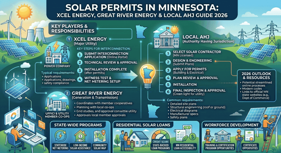
Solar Permits in Minnesota: Xcel Energy, Great River Energy & Local AHJ Guide 2026
Minnesota solar permits require a building permit and an electrical permit from ...
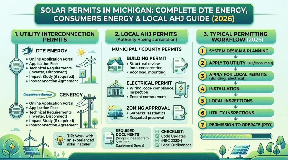
Solar Permits in Michigan: Complete DTE Energy, Consumers Energy & Local AHJ Guide (2026)
Michigan is adding solar faster than most people expect. With residential electr...