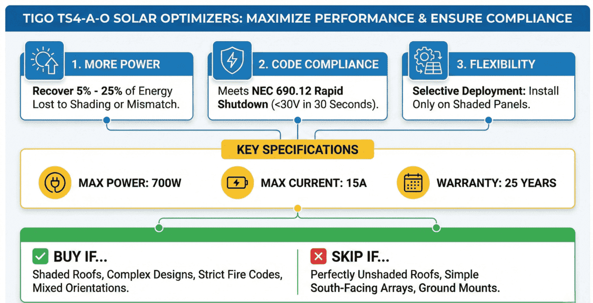
Tigo optimizers are module-level power electronics (MLPEs) that maximize individual solar panel output, enable real-time monitoring, and provide NEC 690.12 rapid shutdown compliance. The TS4-A-O model supports panels up to 700W with 99.6% maximum efficiency and carries a 25-year warranty. Unlike string inverter systems where one shaded panel reduces the entire string output, Tigo optimizers allow each panel to operate at its maximum power point independently, recovering 5% to 25% of energy typically lost to shading, soiling, or panel mismatch.
Tigo optimizers work with string inverters from over 50 manufacturers and offer selective deployment, meaning installers can add optimizers only to shaded panels rather than every module in the array. This flexibility reduces equipment costs while maintaining rapid shutdown compliance required by NEC 2017 and later code editions. The TS4-A-O is UL 1741 PVRSS certified and reduces conductor voltage to 30 VDC or less within 30 seconds of shutdown initiation.
Quick Facts: Tigo TS4-A-O Optimizer
This comprehensive guide examines Tigo optimizer technology, installation requirements per the official TS4-A Installation Manual, and solar permitting considerations. Whether you are a homeowner evaluating equipment options or an installer seeking technical specifications for plan set documentation, this article provides actionable information for module-level optimization decisions.

What Are Tigo Optimizers, and How Do They Work?
Tigo optimizers function as intelligent DC-DC converters installed behind each solar panel in a photovoltaic system. These devices continuously track the maximum power point (MPPT) of individual modules, ensuring each panel operates at peak efficiency regardless of system-wide conditions. The TS4 platform represents Tigo’s fourth-generation technology, offering modular functionality that adapts to specific project requirements.
The TS4-A-O optimizer specifically combines three critical functions: optimization, monitoring, and rapid shutdown. When sunlight hits a solar panel, the optimizer continuously adjusts voltage and current to extract maximum power. This process occurs independently for each panel, preventing underperforming modules from reducing the output of healthy panels in the same string. Understanding how solar energy systems generate electricity helps explain why individual panel optimization significantly impacts total system production.
Core Technology Components
Each TS4-A-O unit contains sophisticated power electronics housed in a weatherproof enclosure rated IP68 and NEMA 3R. The optimizer handles input voltages from 16V to 80V, accommodating virtually all residential and commercial solar modules. Maximum input current reaches 15A at the maximum power point (IMP) and 20A short-circuit current (ISC), supporting high-wattage panels up to 700W.
Wireless communication enables each optimizer to transmit performance data to the monitoring gateway without additional wiring. This architecture simplifies installation while providing comprehensive system visibility. The communication protocol integrates with Tigo’s Cloud Connect Advanced (CCA) and Tigo Access Point (TAP) for remote commissioning and ongoing performance tracking.
TS4-A-O Technical Specifications
Understanding the technical specifications helps determine compatibility with existing equipment and ensures proper system design. The following specifications represent the current TS4-A-O datasheet version 1.4, released November 2023. Before finalizing any design, verify specifications against manufacturer documentation and confirm compatibility with your selected inverter equipment.
Electrical Specifications
Solar Permit Solutions
Affordable Solar Permit Plans
Don't let permit costs slow your project. Professional plan sets at competitive prices — all 50 states, fast turnaround.
Environmental and Mechanical Specifications

Key Benefits of Tigo Optimizers
Tigo optimizers deliver measurable advantages across multiple dimensions of solar system performance. According to SEIA industry research, module-level power electronics continue gaining market share as code requirements expand. The value proposition varies based on site conditions, system size, and local regulatory requirements.
1. Enhanced Energy Harvest Through Individual Panel Optimization
Traditional string inverter systems treat all panels in a string as a single unit, meaning the lowest-performing panel limits the entire string’s output. Tigo optimizers eliminate this constraint by enabling each panel to operate at its individual maximum power point. Real-world installations commonly see 5% to 25% production gains depending on shading conditions and panel mismatch.
Sites with partial shading from trees, chimneys, or neighboring structures benefit most significantly. The optimizer continuously adjusts to changing shade patterns throughout the day, recovering energy that would otherwise be lost. This capability proves particularly valuable for residential solar permitting projects where ideal unshaded roof space is limited.
2. NEC 690.12 Rapid Shutdown Compliance
The National Electrical Code requires photovoltaic systems to reduce conductor voltage to safe levels within 30 seconds of initiating shutdown. The TS4-A-O meets UL 1741 PVRSS certification requirements, reducing conductor voltage to 30V or less outside the array boundary and 80V or less inside the array boundary per NEC 690.12. This compliance is mandatory for permitted installations in jurisdictions that have adopted NEC 2017 or later editions.
Meeting rapid shutdown requirements protects first responders and maintenance personnel from electrical hazards. The TS4 platform uses power line communication (PLC) to receive shutdown signals, requiring no additional control wiring to each optimizer.
3. Module-Level Monitoring and Diagnostics
Each optimizer reports individual panel performance data, including voltage, current, power output, and temperature. This granular visibility enables rapid identification of underperforming modules, reducing troubleshooting time from hours to minutes. The Tigo Energy Intelligence platform displays real-time and historical data through web and mobile interfaces.
Remote monitoring capabilities prove especially valuable for commercial solar projects and O&M service providers managing multiple sites. Automated alerts notify operators of performance anomalies before they significantly impact energy production. This proactive approach to system maintenance maximizes uptime and protects the return on investment.
4. Design Flexibility and Inverter Compatibility
Tigo optimizers work with string inverters from over 50 manufacturers, providing equipment flexibility that microinverter systems cannot match. This compatibility extends to popular inverter brands, including SMA, Fronius, SolarEdge (in non-optimized mode), and many others.
The selective deployment model allows installers to add optimizers only to shaded or problematic panels rather than every module in the array. This approach reduces equipment costs while still capturing the benefits of optimization where it matters most. Solar array design best practices often incorporate this hybrid approach for cost-effective performance optimization.
5. Industry-Leading 25-Year Warranty
The 25-year product warranty matches the expected lifespan of quality solar panels, eliminating concerns about component replacement during the system’s operational period. This warranty coverage reflects Tigo’s confidence in product reliability and reduces long-term ownership costs. Proper equipment warranty documentation should be retained as part of system records.
Installation Requirements and Best Practices
Successful Tigo optimizer deployment requires attention to proper mounting, wiring, and communication setup. The following guidelines are based on the official Tigo TS4-A Installation Manual (Version 2.2) and ensure reliable long-term operation with full compliance to manufacturer specifications and NEC requirements.
Safety Requirements
Tigo equipment must be installed by licensed personnel in accordance with the National Electrical Code and ANSI/NFPA 70 wiring methods. Critical safety requirements include:
• Components must operate within technical specifications listed in datasheets; failure voids warranty coverage
• Connectors from different manufacturers cannot be mated with each other
• Installers must wear appropriate PPE and use insulated tools
• Do not install TS4s if physically damaged or with substandard wiring/connectors
• Do not connect or disconnect TS4s under load
• Do not apply external voltage source to modules or strings equipped with TS4s
TS4-A-O Physical Mounting Requirements
The TS4-A-O mounts directly onto module frames using integrated spring clips. Frame compatibility requires the edge to extend at least 22 mm (0.85 inches) with clearance between the frame edge and module glass of at least 30 mm (1.2 inches). Frame thickness should measure between 1.8 mm and 2.2 mm (0.07 to 0.085 inches). For frameless module installations, remove the clips and bolt the TS4 directly to the PV rail using M8 bolts torqued to 10.2 Nm. No additional grounding is required with this mounting method.
Step-by-Step TS4 Installation Procedure
Follow this sequence precisely to avoid equipment damage:
1. Document placement: Remove the QR/barcode sticker from each TS4 and affix it to a map of the solar array, matching the physical layout of modules on the roof
2. Mount the optimizer: Attach the TS4 to the TOP of the PV module frame using the silver clips with cable glands facing DOWN
3. Connect inputs FIRST: Connect the shorter TS4 input leads to the PV module. This step MUST be completed before connecting to neighboring TS4s
4. Connect string outputs: Connect the longer TS4 output cables to neighboring TS4s to create the string configuration
Safe Disconnection Procedure
When disconnecting TS4 units for maintenance or troubleshooting, follow this mandatory sequence:
5. Activate rapid shutdown by turning off the CCA and inverter, or use the designated PVRSS initiator
6. Wait a minimum of 30 seconds after rapid shutdown activation before disconnecting any DC cables
7. Disconnect individual TS4-A output cables from the string BEFORE disconnecting the TS4-A input cables from the module junction box
Tigo Access Point (TAP) Installation
The TAP communicates wirelessly with TS4 devices to gather monitoring data and enable rapid shutdown. It connects to the CCA via a ferruled 4-wire shielded RS-485 communication cable. Note that TS4-A-O units used solely for optimization without monitoring or module-level shutdown do not require TAP or CCA equipment.
TAP Design Specifications:
• One TAP communicates with up to 300 TS4s when placement guidelines are followed
• Direct communication range: 10 meters (33 feet) to any TS4
• Each TS4 can relay data to another TS4 within 10 meters (33 feet)
• Maximum relay distance: 35 meters (115 feet) between TAP and farthest TS4
• Install TAP centrally in the array for optimal coverage; multiple roof planes may require multiple TAPs
Cloud Connect Advanced (CCA) Installation
The CCA serves as the system gateway, enabling monitoring and rapid shutdown functionality. It should control all TS4s on strings connected to a specific inverter or MPPT. Install the CCA near the inverter with access to AC power and internet connectivity (Ethernet and WiFi built in).
Critical CCA Design Requirements:
• PVRSS Compliance: The CCA MUST be on the same AC branch circuit as the inverter(s) it controls
• One CCA communicates with up to 7 TAPs and 900 TS4s maximum
• Complete ALL TAP connections before powering on the CCA
• Mount CCA in NEMA-rated enclosure: indoor minimum NEMA 1, outdoor minimum NEMA 4
CCA LED Status Indicators
Understanding CCA LED indicators helps with troubleshooting and system verification during commissioning and ongoing operation:
System Commissioning
System configuration and registration are performed through the Tigo Energy Intelligence (EI) platform, accessible via web browser at ei.tigoenergy.com or through the mobile app available on the App Store and Google Play. Final commissioning requires the Tigo EI mobile app.
For detailed commissioning instructions and troubleshooting, visit the Tigo support portal or contact Tigo support. Understanding electrical permit requirements ensures all necessary components and documentation are prepared for AHJ inspection.
Are Tigo Optimizers Worth the Investment?
The value proposition for Tigo optimizers depends on site-specific factors, including shading conditions, system size, local code requirements, and available alternatives. Tools like the NREL PVWatts Calculator can help estimate baseline production, while optimization gains require site-specific shading analysis.
When Optimizers Provide Strong ROI
• Shaded installations: Sites with partial shading from trees, adjacent structures, or rooftop obstructions see the greatest production gains. Energy recovery of 15% to 25% is common in moderately shaded conditions.
• Complex roof geometries: Multiple roof planes with different orientations or tilts benefit from individual panel optimization rather than string-level control.
• Rapid shutdown compliance: When code requires module-level shutdown, optimizers often cost less than alternative compliance methods while adding monitoring and optimization benefits.
• Commercial O&M requirements: Large installations benefit from reduced troubleshooting time and proactive maintenance enabled by module-level monitoring.
• System expansion projects: Adding panels with different specifications to existing arrays requires individual optimization to prevent mismatch losses.
ROI and Payback Considerations
Determining whether Tigo optimizers provide positive ROI requires site-specific analysis. The investment typically pays back within 3 to 7 years under the following conditions:
Strong ROI scenarios (3-5 year payback):
- Moderate to heavy shading affecting 20%+ of production
- High local electricity rates ($0.20+ per kWh)
- Systems where rapid shutdown compliance is already required
- Commercial installations with O&M monitoring requirements
Marginal ROI scenarios (7+ year payback):
- Light or no shading conditions
- Lower electricity rates
- Ground-mount installations with minimal obstructions
- Systems where only rapid shutdown compliance is needed
For installations requiring NEC 690.12 rapid shutdown compliance, the incremental cost to upgrade from TS4-A-F (shutdown only) to TS4-A-O (full optimization) is approximately $20 to $25 per panel. This modest premium often justifies full optimization even in lightly shaded
How Much Do Tigo Optimizers Cost?
Tigo optimizer pricing varies based on the specific model, quantity purchased, and whether you need the complete monitoring infrastructure. Understanding the full cost picture helps determine whether the investment makes sense for your specific installation.
TS4-A-O Optimizer Unit Costs
Individual TS4-A-O optimizers typically cost between $50 and $85 per unit at retail pricing. Wholesale pricing for installers purchasing in volume (25+ units) often falls in the $40 to $60 range. The exact price depends on cable length configuration and connector type (MC4 vs EVO2).
Required Infrastructure Costs
Beyond the optimizers themselves, most installations require additional Tigo communication equipment for monitoring and rapid shutdown functionality. These components represent a fixed cost regardless of system size.
When Optimizers May Not Be Necessary
Unshaded arrays with uniform panel orientation may not justify optimizer costs beyond what is needed for code compliance. Ground-mount installations with optimal spacing and no obstructions typically see minimal production benefit from optimization. In these scenarios, basic rapid shutdown solutions may provide required compliance at a lower cost.
Understanding your specific solar installation costs and projected energy production helps quantify the optimizer value proposition. Professional solar design services can model expected production with and without optimization to inform equipment decisions.
Tigo vs. Other MLPE Solutions
The module-level power electronics market includes several competing technologies. Understanding the differences helps select the optimal solution for specific project requirements.
DC Optimizers vs. Microinverters
Tigo optimizers maintain DC architecture, pairing with string or central inverters for DC-to-AC conversion. Microinverters perform this conversion at each panel. The DC optimizer approach typically offers higher system efficiency (99.6% for Tigo vs. 96-97% for most microinverters) and lower per-watt costs at scale. However, microinverters simplify system design and eliminate single points of failure.
For larger residential and commercial installations, DC optimizers with string inverters often provide better economics. Smaller residential systems may favor microinverters for simplicity. The DOE Homeowner’s Guide to Solar provides additional guidance on equipment selection for residential installations.
Tigo Selective Deployment Advantage
Unlike SolarEdge systems that require optimizers on every panel, Tigo enables selective deployment where optimizers are installed only on affected modules. This flexibility reduces equipment costs for partially shaded arrays while maintaining rapid shutdown compliance system-wide. The TS4-A-F (flex) units provide rapid shutdown for unshaded panels without full optimization capability at a lower cost.

Tigo vs SolarEdge vs Enphase: Which Is Best?
Choosing between Tigo optimizers, SolarEdge power optimizers, and Enphase microinverters depends on your specific installation requirements, budget constraints, and long-term system goals. Each technology offers distinct advantages for different use cases.
Technology Architecture Comparison
The fundamental difference lies in how each system handles power conversion and optimization.
Tigo TS4-A-O: DC-DC optimizer that pairs with any compatible string inverter. The optimizer handles maximum power point tracking at the panel level while the string inverter performs DC-to-AC conversion. This distributed architecture means the inverter’s MPPT handles most of the heavy lifting, with Tigo optimizers activating primarily when panel mismatch or shading occurs.
SolarEdge Power Optimizers: DC-DC optimizers that work exclusively with SolarEdge inverters. Unlike Tigo, SolarEdge optimizers perform continuous voltage regulation on every panel because SolarEdge inverters lack traditional MPPT functionality. The inverter relies entirely on the optimizers for power point tracking.
Enphase Microinverters: Complete DC-to-AC conversion occurs at each panel. No central inverter exists, each microinverter operates as an independent grid-tie unit. This architecture provides maximum panel independence but at higher cost and slightly lower conversion efficiency.