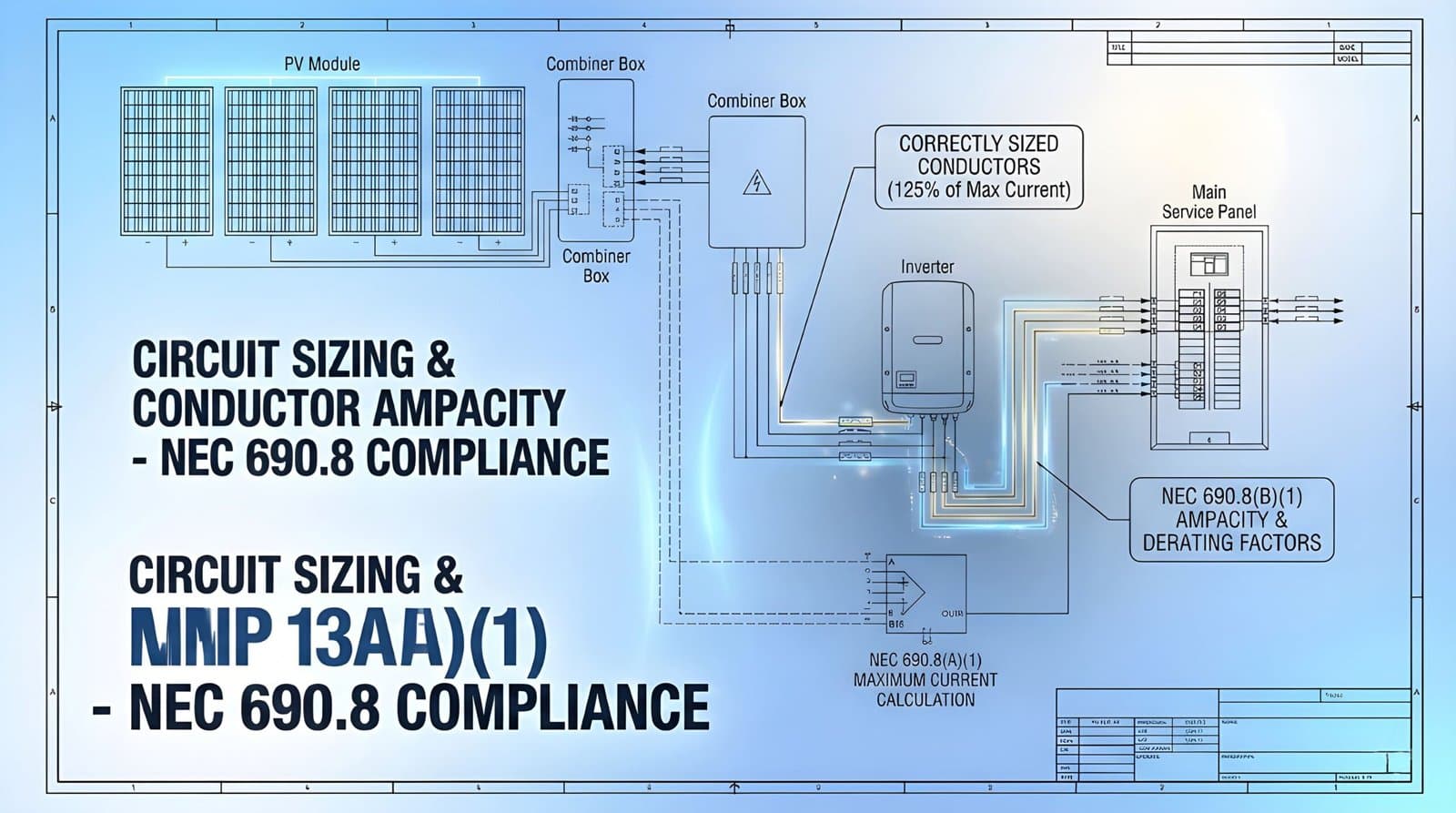
NEC 690.8 establishes the circuit sizing and protection requirements for photovoltaic power systems under the 2023 National Electrical Code. This code section mandates that all PV circuit conductors must be sized to carry at least 125% of the maximum calculated current, with additional derating for temperature conditions and conduit fill when applicable.
The code covers four critical areas: conductor ampacity calculations based on module short-circuit current (Isc), overcurrent protection device sizing that cannot exceed manufacturer specifications, voltage drop considerations for system efficiency, and proper conductor identification for grounding and circuit polarity. Violations of NEC 690.8 account for 30-40% of all solar permitting rejections nationwide, making it the most frequently cited code section during electrical inspections.
Common compliance failures stem from three calculation errors: forgetting to apply the 125% continuous current multiplier before temperature corrections, overlooking cumulative derating when multiple correction factors apply simultaneously, and exceeding the maximum series fuse rating listed on module datasheets. Understanding these requirements prevents permit delays, ensures system safety, and maintains code compliance across residential, commercial, and utility-scale installations in all 50 states.
Note: This guide references the 2023 NEC. Some jurisdictions may still operate under the 2020 NEC or have adopted future amendments. Always verify current code requirements with your local Authority Having Jurisdiction before submitting permit applications.
The Most Common NEC 690.8 Violations Found During Inspections
Authority Having Jurisdiction (AHJ) inspectors consistently flag specific NEC 690.8 violations during plan reviews and field inspections. Understanding these common issues helps installers avoid costly delays and rework.
Recent industry surveys from solar permitting professionals reveal that circuit-related violations account for approximately 30-40% of all NEC 690 code issues. The most frequently cited problems include:
- Improper conductor ampacity calculations that fail to account for temperature correction factors
- Inadequate overcurrent protection device sizing for maximum circuit current
- Voltage drop calculations that exceed allowable thresholds
- Missing or incorrect circuit identification and labeling
- Conduit fill violations when multiple PV source circuits share raceways
National electrical inspection data shows that circuit sizing errors represent the largest category of NEC 690.8 violations. Many installers incorrectly apply the 125% multiplier or overlook the cumulative effect of continuous current, ambient temperature correction, and conduit fill adjustments.
These seemingly minor calculation errors can result in undersized conductors that pose fire risks and system failures. For example, a 10 AWG conductor rated for 30 amperes at 30°C drops to only 21 amperes when temperature corrections and conduit fill derating both apply.
Field inspections consistently uncover installations where contractors used residential wiring methods for commercial-scale systems or applied incorrect ampacity tables. The consequences extend beyond failed inspections to include potential safety hazards, insurance complications, and reduced system performance over time.

Breaking Down NEC 690.8 Code Requirements
NEC 690.8 establishes comprehensive circuit requirements that apply to all photovoltaic system installations. Understanding these requirements in context helps installers design compliant systems from the start.
Circuit Current Calculations
The 2023 NEC 690.8(A)(1) requires PV circuit conductors to carry 125% of the maximum current calculated under specific conditions. This continuous current rating applies to all conductors between modules and the first overcurrent device. Installers must calculate maximum circuit current using the module short-circuit current (Isc) multiplied by 125%, then apply additional correction factors based on installation conditions.
Here’s a practical example: A module with 11.5A Isc in a string configuration requires conductors rated for at least 14.4A (11.5A × 1.25 = 14.4A) before any correction factors. If the installation uses rooftop conduit at 50°C ambient temperature, NEC Table 310.15(B)(1) requires applying a 0.58 temperature correction factor. The conductor must now handle 24.8A (14.4A ÷ 0.58 = 24.8A).
Temperature correction factors significantly impact conductor sizing. PV systems typically operate at elevated temperatures due to rooftop mounting and solar radiation. The NEC requires ampacity adjustments when ambient temperatures exceed 30°C (86°F).
For conductors rated at 90°C in 40°C ambient conditions, apply a 0.91 correction factor. At 50°C, the factor drops to 0.82. Failure to apply these corrections results in undersized conductors that can overheat under normal operating conditions.
Overcurrent Protection Requirements
NEC 690.8(B) mandates overcurrent protection for PV circuits, with specific sizing criteria. Overcurrent protective devices must handle the calculated maximum circuit current without nuisance tripping while providing adequate fault protection. The code permits oversizing up to the next standard rating when calculated values fall between standard device sizes.
Series fuse sizing presents particular challenges for installers. The maximum series fuse rating appears on module specification sheets, and installers cannot exceed this value regardless of circuit calculations. This requirement often constrains system design and requires careful attention during the planning phase.
Voltage Drop Considerations
While NEC 690.8 does not explicitly mandate voltage drop limits, Article 210.19(A) Informational Note No. 4 recommends keeping voltage drop to 3% for branch circuits. Many AHJs enforce voltage drop requirements for PV systems, particularly for longer wire runs from array to inverter. Excessive voltage drop reduces system efficiency and can cause inverter operational issues.
Installers should calculate voltage drop for both DC and AC circuits, accounting for conductor length, amperage, and conductor material. Online calculators and design software help streamline these calculations, but understanding the underlying principles remains essential for troubleshooting and field modifications.
Conduit and Raceway Requirements
NEC 690.8 works in conjunction with Chapter 3 requirements for conduit fill and conductor protection. PV source circuits sharing a raceway must account for additional ampacity derating based on the number of current-carrying conductors.
Per NEC Table 310.15(B)(3)(a), when 4-6 current-carrying conductors occupy a raceway, apply an 80% adjustment factor. For 7-9 conductors, the factor drops to 70%. This derating factor compounds with temperature corrections, potentially requiring significant conductor upsizing.
Consider this scenario: A 10 AWG USE-2 conductor rated for 40A at 90°C must be derated to 32A (40A × 0.80) when six conductors share conduit. Apply an additional 0.82 temperature correction for 50°C ambient, and the effective ampacity drops to just 26.2A. The installer may need to upsize to 8 AWG to meet code requirements.
Many jurisdictions require PV conductors to run in metallic conduit for mechanical protection and grounding continuity. Proper conduit sizing prevents conductor damage during installation and allows for future maintenance. Undersized conduits create installation difficulties and may violate NEC 300.17 requirements for conductor protection.
Conductor Types and Equipment Grounding
NEC 690.8(C) addresses conductor identification and equipment grounding requirements specific to PV installations. PV source and output circuits require conductors rated for wet locations and sunlight resistance. USE-2 and PV Wire meet these requirements and carry a 90°C temperature rating suitable for rooftop installations.
Equipment grounding conductors must comply with NEC 250.122 sizing requirements based on the rating of the overcurrent protective device. For circuits protected by a 20A breaker, the equipment grounding conductor must be at least 12 AWG copper. When circuit conductors upsize due to voltage drop or long runs, many AHJs require proportional equipment grounding conductor sizing per NEC 250.122(B).
Proper conductor color coding prevents installation errors and satisfies inspection requirements. White or gray conductors indicate grounded conductors, while green or bare copper designates equipment grounding conductors. Some jurisdictions require red and black for positive and negative PV circuit conductors respectively.
Step-by-Step Calculation Example
Understanding NEC 690.8 compliance becomes clearer through a complete calculation example. Consider a string of modules with these specifications: 11.5A Isc, maximum series fuse rating 20A, installed in rooftop conduit at 50°C ambient temperature with six current-carrying conductors.
Step 1: Calculate continuous current: 11.5A × 1.25 = 14.4A
Step 2: Apply temperature correction (50°C): 14.4A ÷ 0.82 = 17.6A
Step 3: Apply conduit fill derating (6 conductors): 17.6A ÷ 0.80 = 22A
Step 4: Select conductor: 10 AWG copper at 90°C (40A) meets the 22A requirement after all derating
Step 5: Verify overcurrent protection: 20A breaker or fuse does not exceed module’s maximum series fuse rating
This systematic approach prevents the calculation errors that cause most NEC 690.8 violations. Document each step for permit submittal and field reference.
Conductor Sizing Comparison Table
The table below shows how different installation conditions affect conductor sizing for a typical solar installation. All scenarios assume a module with 11.5A Isc and 90°C rated copper conductors.
Key Takeaways from the Table:
- Temperature and conduit fill corrections compound, not add
- A single 10 AWG conductor works in many scenarios, but upsizing to 8 AWG becomes necessary with multiple derating factors
- Extreme conditions (60°C + high conduit fill) can require two or more conductor size increases
- Always calculate the required ampacity before selecting conductor size

Proven Strategies For Achieving NEC 690.8 Compliance
Achieving consistent compliance with NEC 690.8 circuit requirements demands systematic approaches to design, installation, and verification. The following strategies help installers avoid common violations and streamline the permitting process.
Implement Thorough Design Review
Begin every project with comprehensive circuit calculations that document all adjustment factors. Use standardized calculation worksheets that capture module specifications, environmental conditions, conductor routing, and protection device ratings. This documentation proves invaluable during plan reviews and serves as a reference for field installers.
Design software tools automate many calculations but require operator understanding to produce accurate results. Verify software outputs manually for critical circuits or unusual installations. Cross-reference manufacturer specifications, particularly for temperature ratings and maximum overcurrent protection device sizes.
Apply Correction Factors Systematically
Create a consistent workflow for applying temperature corrections, conduit fill adjustments, and continuous current multipliers. Many violations stem from missing a single correction factor in multi-step calculations. A standardized checklist ensures installers account for all required adjustments before finalizing conductor sizing.
Pay particular attention to cumulative effects when multiple correction factors apply. A conductor that meets code requirements before corrections may require two or three size increases after applying all adjustment factors.
This reality often surprises installers accustomed to residential work where such extensive derating rarely occurs. Commercial and utility-scale installations frequently require 8 AWG or larger conductors where 10 AWG initially seemed adequate.
Maintain Detailed Installation Records
Document all circuit measurements, wire routing decisions, and protection device settings during installation. This documentation supports inspection requests, troubleshooting efforts, and future system modifications. Photographs of conductor terminations, conduit routing, and labeling prove particularly valuable for resolving questions that arise after inspection.
Include voltage drop measurements in commissioning records, even when not explicitly required. These baseline measurements help diagnose performance issues and verify design calculations. Many system problems that appear complex trace back to excessive voltage drop in DC or AC circuits.
Stay Current With Code Updates
NEC updates occur on a three-year cycle, with many jurisdictions adopting new editions within 1-2 years of publication. The 2023 NEC introduced several clarifications to Article 690, including refined language around circuit protection and conductor sizing. Installers must track which NEC edition applies in each jurisdiction and understand the specific amendments adopted locally.
Many states and municipalities maintain online resources documenting their adopted electrical code edition and local amendments. Check these resources during project planning to avoid designing systems based on outdated or incorrect code requirements. When questions arise, contact the local AHJ directly for clarification rather than relying on assumptions.
Partner With Engineering Support
Complex projects benefit from professional electrical engineering review, particularly for large commercial installations or unusual system configurations. Licensed electrical engineers can stamp design documents, calculate fault currents, and provide detailed single-line diagrams that satisfy stringent AHJ requirements.
Solar Permit Solutions provides comprehensive electrical engineering for PV installations nationwide. Professional design review identifies potential NEC 690.8 violations before submitting permit applications, reducing approval times and eliminating costly field modifications. Engineering support proves especially valuable when dealing with unfamiliar jurisdictions or technically challenging installations.
Get Expert Help With NEC 690.8 Compliance
Navigating complex circuit calculations and varying AHJ requirements can delay projects and increase costs. Solar Permit Solutions specializes in NEC-compliant solar permit packages that pass inspection on the first submission. Our licensed engineers handle all conductor sizing calculations, overcurrent protection specifications, and voltage drop analysis to ensure your installations meet code requirements.
Whether you need full permit design services, engineering stamps, or technical review of existing plans, our team has processed thousands of solar permits across all 50 states. Contact us today to discuss your project and get a quote for professional permit support that eliminates code compliance headaches.
Solar Permit Solutions
Skip the Permit Headaches
We design plan sets that pass inspection the first time. Code-compliant, PE-stamped, accepted by AHJs nationwide.
Conclusion
NEC 690.8 circuit requirements establish essential safety standards for photovoltaic system installations. While these requirements may seem complex, systematic application of code provisions ensures both compliance and system safety.
Common violations typically stem from incomplete calculations rather than misunderstanding of fundamental principles. By implementing thorough design review processes, applying correction factors consistently, and maintaining detailed records, installers can achieve reliable NEC 690.8 compliance across all project types.
Staying current with code updates and leveraging professional engineering support when needed further strengthens compliance efforts and reduces project risks.
FAQs
Installers must first calculate the maximum circuit current using module short-circuit current, then multiply by 125% before applying any temperature or conduit fill correction factors. This requirement ensures conductors can safely handle sustained operation without overheating.
Even if circuit calculations suggest a larger overcurrent device, the module specification takes precedence. Exceeding this rating voids module warranties and creates serious safety hazards.
When system design requires higher current capacity, installers must add parallel strings rather than oversizing series fuses.
The 2023 NEC Table 310.15(B)(1) provides correction factors for various temperature ranges. Many jurisdictions require worst-case temperature assumptions for permit submittals.
Failing to apply proper temperature corrections results in undersized conductors that violate code and create fire risks.
Second, when more than three current-carrying conductors occupy a single raceway, additional ampacity derating applies per NEC 310.15(B)(3)(a). This derating compounds with temperature corrections, often requiring significant conductor upsizing.
For example, six current-carrying conductors in a conduit require 80% ampacity derating, while nine conductors require 70% derating.
Single-line diagrams must clearly identify all circuits, protection devices, and conductor sizes. Many jurisdictions also require load calculations, fault current studies, and arc flash analysis for commercial installations.
Submitting complete documentation upfront prevents plan review delays and demonstrates professional-level engineering. Solar Permit Solutions provides comprehensive permit packages that include all required NEC 690.8 documentation formatted to meet specific AHJ requirements.
Some rapid shutdown devices introduce additional current-carrying conductors that affect conduit fill calculations and ampacity derating. However, the fundamental 125% continuous current requirement and temperature correction factors still apply regardless of rapid shutdown method.
Installers must account for all system components when performing NEC 690.8 calculations to ensure proper conductor sizing throughout the entire array.


