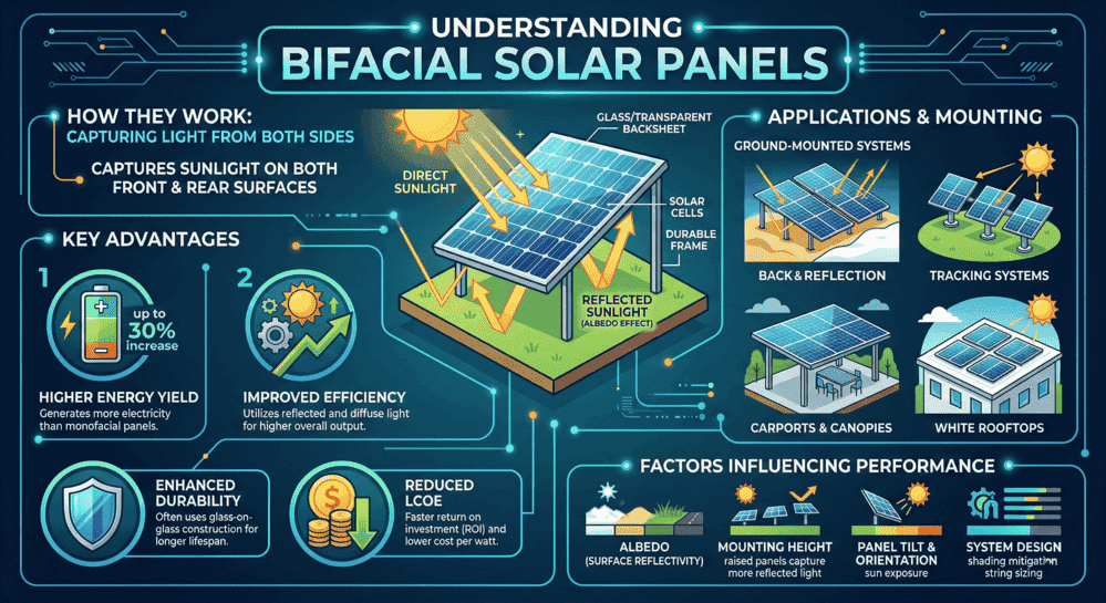
Bifacial solar panels generate 10 to 30 percent more energy than traditional monofacial panels by capturing sunlight on both the front and rear surfaces, but that gain only materializes when the system is correctly installed and permitted.
A bifacial solar panel is a photovoltaic module with active cells on both its front glass and rear surface. The front side captures direct sunlight. The rear side captures light reflected off the ground, a feature called albedo gain. Most commercial bifacial panels have a bifaciality factor between 70 and 90 percent, meaning the rear surface can generate 70 to 90 percent of what the front side produces under identical light conditions. According to the U.S. Department of Energy, bifacial technology has demonstrated the potential to increase system outputs by 10 to 20 percent, and field deployments with high-albedo surfaces have recorded gains above 25 percent.
Key facts for installers and permit applicants:
- Minimum mounting height: 1.0 meter ground clearance to the bottom of the panel, with 1.2 to 1.3 meters being the optimal range for most installations
- Ground Coverage Ratio (GCR): 0.30 to 0.50 for bifacial systems, wider than standard monofacial layouts
- Best surface albedo: White concrete (0.70 to 0.80) and white gravel (0.55 to 0.70) deliver the highest rear-side gain
- Electrical code: NEC Article 690.8 requires bifacial-enhanced Isc to be factored into conductor and overcurrent device sizing
- Permit requirement: Elevated ground mounts typically require PE-stamped structural drawings and foundation load calculations not required for standard rooftop systems
- Cost premium: Bifacial systems run $0.08 to $0.18 per watt more than equivalent monofacial installations, primarily due to elevated racking and ground preparation
- Degradation advantage: Glass-on-glass bifacial panels degrade at less than 0.40 percent per year versus 0.50 to 0.70 percent for standard panels
This guide covers how to install bifacial solar panels step by step, how to design mounting systems for maximum bifacial gain, and exactly what a bifacial solar panel permit plan set must include to pass AHJ review across all 50 states.
What Are Bifacial Solar Panels?
Bifacial solar panels contain photovoltaic cells on both the front and rear surfaces. The front side captures direct sunlight as a conventional panel does. The rear side captures light that reflects off the ground or nearby surfaces and passes back through the mounting gap. This reflected light, known as albedo, is what gives bifacial panels their energy production advantage.
Most bifacial panels use a glass-on-glass construction, replacing the traditional opaque backsheet with a second layer of tempered glass. Some models use a transparent polymer backsheet instead, which reduces weight but may degrade faster under prolonged UV exposure. According to NREL research, the choice between these two constructions affects installation handling requirements, long-term durability, and rear-side optical performance.
A key specification is the bifaciality factor, which measures how effectively the rear side generates power relative to the front side. A bifaciality factor of 75 percent means the rear surface can produce up to 75 percent of the front-side rated power under identical irradiance conditions. Most commercial bifacial panels on the market today have bifaciality factors between 70 and 90 percent.
Bifacial panels must meet the same certification standards as monofacial panels, including UL 61730 or IEC 61215 and IEC 61730 for safety and performance. The IEC has developed supplementary test conditions specifically for bifacial modules to account for the higher current flows that occur under dual-illumination conditions.
Bifacial vs. Monofacial: Which Is Right for Your Installation?
Choosing between bifacial and monofacial panels depends on the installation type, site conditions, and budget. The table below summarizes the key differences.
| Factor | Bifacial Panels | Monofacial Panels |
| Energy gain | 10 to 25 percent additional from rear side (site-dependent) | Baseline, front side only |
| Cost | 10 to 20 percent premium on panel cost | Lower upfront cost |
| Construction | Glass-on-glass or glass with transparent backsheet | Glass with opaque backsheet |
| Best application | Ground mounts, carports, flat commercial rooftops with white membrane | Pitched residential rooftops |
| Mounting complexity | Higher, requires elevated racking with clearance optimization | Standard racking systems |
| Permit complexity | Higher, elevated mounts trigger additional structural review | Standard process in most jurisdictions |
| Typical warranty | 25 to 30 years from most tier-1 manufacturers | 25 years standard |
| Weight (glass-on-glass) | 25 to 32 kg per panel, roughly 15 to 20 percent heavier | Lower, easier to handle |
Bifacial panels are most cost-effective in ground-mounted commercial systems with reflective surfaces below, elevated carport or canopy structures, flat commercial rooftops with white TPO or PVC membrane, and installations in regions with snow, sand, or light-colored soils. Standard residential pitched rooftops with limited rear clearance and dark shingles beneath the panels see minimal bifacial gain, making monofacial panels the more practical choice in those scenarios. For help sizing either system type, visit the Solar Permit Solutions services page.
Best Applications for Bifacial Solar Panels
Understanding where bifacial technology excels helps you make the right recommendation for each project.
Ground-Mounted Commercial Systems
This is where bifacial panels deliver the highest gain. Ground mounts allow full control over height, tilt, row spacing, and ground surface. According to a global performance study published at NREL, elevating panels 1 meter above ground with an albedo of 0.50 can boost bifacial gain to 30 percent. With white gravel or concrete beneath the array and 1.2 to 1.5 meters of clearance, real-world bifacial gain in the 18 to 25 percent range is routinely achievable on well-designed systems. For full engineering support on commercial ground mount solar design, Solar Permit Solutions delivers PE-stamped plan sets for all 50 states.
Carports and Canopy Structures
Bifacial panels on elevated carport structures benefit from an open underside and diffuse light reflection off concrete or asphalt beneath. Even with lower-albedo surfaces like asphalt, the open geometry provides consistent rear-side irradiance. Carport heights of 2.5 meters or more also make maintenance access straightforward.
Agrivoltaic and Dual-Use Installations
Bifacial panels are increasingly used in agrivoltaic projects, where the array is elevated high enough for crops or grazing to continue beneath. The U.S. Department of Energy has funded agrivoltaic research at 29 sites nationwide, finding that in high-heat regions such as the desert southwest, crop yield can increase and irrigation requirements can decrease when panels provide beneficial shade. These installations require specialized structural engineering and often involve state agricultural agencies in the permitting process.
Flat Commercial Rooftops
White membrane roofing materials such as TPO and PVC have albedo values of 0.60 to 0.80, making them well-suited for bifacial rear-side gain. Low-slope commercial rooftops with ballasted racking systems can achieve bifacial gains of 10 to 18 percent. These systems require careful attention to mounting clearance above the membrane surface and waterproofing at all penetration points.
Vertical Building-Integrated Installations
Bifacial panels installed vertically on building facades or as glass curtain walls capture morning and evening sun on alternating sides. While total energy output is lower than tilted ground mounts, vertical bifacial installations serve dual purposes as building envelope and power generation and offer unique architectural benefits.
Off-Grid Systems
Bifacial panels are also viable for off-grid applications. Elevated ground mounts in remote locations can take full advantage of high-albedo surfaces like natural stone, light soil, or seasonal snow. For off-grid permit design and plan sets, Solar Permit Solutions offers dedicated off-grid solar system design services.
Solar Permit Solutions
Skip the Permit Headaches
We design plan sets that pass inspection the first time. Code-compliant, PE-stamped, accepted by AHJs nationwide.
Pre-Installation Site Assessment for Bifacial Systems
A thorough site assessment for bifacial panels goes beyond standard solar evaluation. You need to assess not just direct irradiance but also what the rear side of the panel will receive throughout the year.
Ground Surface Reflectivity (Albedo)
Albedo is the most important site-specific variable for bifacial performance. The table below shows common surface albedo values.
| Surface Type | Albedo Value | Bifacial Suitability |
| Fresh snow | 0.80 to 0.90 | Excellent, seasonal boost |
| White concrete | 0.70 to 0.80 | Excellent, preferred for permanent installs |
| White gravel or marble chips | 0.55 to 0.70 | Very good, cost-effective and durable |
| Light sand | 0.35 to 0.45 | Good, regional advantage in desert climates |
| Dry grass or light vegetation | 0.20 to 0.30 | Moderate, maintain height below 6 inches |
| Aged concrete | 0.25 to 0.40 | Moderate |
| Dark soil | 0.05 to 0.15 | Poor, minimal bifacial benefit |
| Asphalt | 0.05 to 0.10 | Poor, not recommended for bifacial optimization |
Structural and Height Constraints
Determine the maximum achievable ground clearance at the site. Ground obstructions, local zoning height limits, and structural engineering constraints all affect how high the racking system can go. Systems with less than 0.50 meters of clearance will see minimal bifacial gain and may not justify the premium over monofacial panels.
Shading Analysis: Front and Rear
Standard shading analysis tools such as Aurora, Helioscope, and PVsyst can model front-side shading. For bifacial systems, you also need to evaluate rear-side shading sources including mounting rails, cable runs, cross-members, and adjacent structures. Rear-side obstructions that cover more than 10 percent of the panel area will measurably reduce bifacial gain.
Climate and Seasonal Conditions
Regions with snow provide seasonal albedo boosts that can significantly increase annual bifacial gain. Desert climates with light sandy soils benefit year-round. Humid climates with dark, wet soils see the least bifacial advantage. Model seasonal variation in your production estimates rather than applying a single annual albedo value. The NREL bifacial research program has documented how seasonal ground conditions, including snow cover and vegetation color changes, produce meaningful variation in rear-side irradiance throughout the year.
Bifacial Solar Panel Mounting: Height, GCR, and Racking Requirements
Minimum Height Requirements
Height is the single most impactful installation variable for bifacial performance. Industry practice calls for a minimum of 1.0 meter of clearance from the ground surface to the bottom of the panel, with 1.2 to 1.3 meters being the range where most systems achieve optimal rear-side irradiance. Systems installed at 1.5 to 2.0 meters see the highest bifacial gains. Below 0.50 meters, bifacial gain drops sharply and may fall below 5 percent, negating the technology’s advantage over standard monofacial panels.
The NREL global optimization study confirms that increasing module height from ground level to 1.0 meter above ground, combined with an albedo of 0.50, can boost bifacial gain to 30 percent compared to under 10 percent at low albedo and minimal clearance.
Ground Coverage Ratio (GCR) Optimization
Ground Coverage Ratio is calculated as panel width divided by row spacing. For bifacial systems, a lower GCR than standard monofacial designs is recommended because wider row spacing allows more reflected light to reach rear surfaces and reduces inter-row shading on the rear face of panels.
- High-albedo sites (white gravel, snow): GCR 0.30 to 0.40
- Standard sites (maintained grass, aged concrete): GCR 0.40 to 0.50
- Lower-albedo sites where bifacial gain is secondary: GCR 0.45 to 0.55
For example, a system using 2.1-meter wide panels targeting a GCR of 0.40 requires 5.25-meter row spacing. This is significantly wider than the same panels would require in a monofacial layout optimized for a GCR of 0.55. See the Solar Permit Solutions ground mount design guide for detailed engineering guidance on row spacing, pile spacing, and foundation design.
Racking System Selection
Standard residential racking systems are not designed for bifacial optimization. For ground-mounted bifacial, racking systems should provide minimal rail contact with the panel rear surface, use narrow rail profiles to reduce rear-side shadow casting, achieve the necessary height clearance, and accommodate glass-on-glass panel weight (typically 25 to 32 kg per panel). For bifacial racking system requirements in your permit plan set, see the Solar Permit Solutions commercial solar design page.
Frameless vs. Framed Panel Mounting
Frameless bifacial panels require specialized clamps that grip the panel glass edge directly rather than an aluminum frame. These clamps must be positioned within the manufacturer-specified distance from the panel corner, typically within 200 mm, to avoid mechanical stress on the glass. Always verify manufacturer installation instructions before selecting mounting hardware for frameless bifacial panels.

How to Install Bifacial Solar Panels: Step-by-Step Process
Step 1: Site Preparation and Foundation Work
- Survey and stake out array footprint per engineering drawings
- Excavate foundation locations to required depth, typically 1.2 to 1.8 meters for driven piles or helical anchors depending on soil conditions and structural engineering specifications
- Install foundations and allow concrete to cure (minimum 7 days) before loading with racking
- Prepare ground surface: grade for 1 to 2 percent drainage slope, install landscape fabric, apply white gravel to a 75 to 100 mm depth if using reflective ground cover
Step 2: Racking and Mounting Structure Assembly
- Assemble post and beam structure per structural engineering drawings
- Verify all mounting heights meet minimum 1.0-meter clearance (1.2 to 1.3 meters preferred) before securing structural connections
- Check row spacing and alignment against GCR calculations
- Torque all hardware connections to manufacturer specifications and document torque values for the inspection record
Step 3: Panel Installation
- Inspect each panel for damage before mounting and document any pre-existing defects
- Use proper lifting equipment for glass-on-glass panels. Never support panels by the junction box
- Secure panels using clamps positioned per manufacturer specifications
- Maintain consistent inter-panel gaps for thermal expansion, typically 5 to 10 mm minimum
- Verify no mounting hardware, cables, or conduit runs across the panel rear surface in high-irradiance zones
Step 4: Electrical Wiring
- Route all DC wiring along panel edges and racking members. Avoid running cables across the rear face of panels
- Use underground conduit for wire runs between rows where possible
- Install combiners, disconnects, and inverter per the approved electrical plan set
- Install power optimizers or microinverters if specified. These are particularly valuable for bifacial systems where rear-side irradiance varies between rows and at different times of day
Step 5: Testing and Commissioning
- Perform visual inspection of all mechanical connections and wiring
- Measure open-circuit voltage and short-circuit current for each string
- Verify proper grounding continuity on all metallic components per NEC Article 690.43
- Test rapid shutdown functionality per NEC Article 690.12
- Commission monitoring system and establish performance baseline. For NEC Article 690 compliance requirements specific to bifacial systems, refer to the Solar Permit Solutions NEC 2023 compliance guide
Bifacial Solar Panel Permitting: What the Permit Plan Set Must Include
This section covers the most significant gap left by competing installation guides. Bifacial solar panel permitting has specific requirements that differ from standard rooftop installations. Treating a bifacial ground mount like a standard rooftop system in a permit application almost always generates plan check comments and delays.
Why Bifacial Systems Create Unique Permitting Challenges
Most AHJs have standardized review processes for residential rooftop solar. Bifacial ground mounts and elevated commercial systems introduce variables these standard processes were not designed to evaluate: greater structural heights, specialized racking loads, enhanced electrical output per string, and sometimes zoning implications from taller structures. Understanding these upfront reduces costly revisions. For a broader overview of the permit process, see the Solar Permit Solutions permit requirements guide.
Structural Engineering Documentation
Elevated bifacial racking systems require engineering documentation beyond standard residential solar. Your plan set should include:
- Foundation design calculations accounting for height-amplified wind loads (taller structures are exposed to higher wind uplift forces per ASCE 7-22, the structural standard referenced in the 2024 International Building Code)
- Racking dead load calculations reflecting glass-on-glass panel weight, typically 25 to 32 kg per panel, 15 to 20 percent heavier than most monofacial panels
- Seismic load analysis where applicable, because elevated center of gravity changes seismic design requirements
- Soil bearing capacity documentation for pile or anchor foundations
- PE stamp from a licensed structural engineer when racking height exceeds local thresholds (commonly triggered at heights above 1.8 to 2.4 meters in most jurisdictions). See the Solar Permit Solutions structural engineering calculations guide for PE stamp triggers by project type
For detailed information on which states require PE stamps and at what project thresholds, the Solar Permit Solutions PE stamp requirements by state guide covers all 50 states.
Electrical Plan Set Requirements for Bifacial Systems
Bifacial panels can generate more power per panel under real-world conditions than the nameplate DC STC rating suggests, because rear-side irradiance adds to total panel output. This affects several electrical design elements that must be reflected in the permit drawings. The National Electrical Code (NEC) Article 690 governs all PV system electrical design:
- NEC 690.8 maximum circuit current: conductor and overcurrent device sizing must account for the elevated Isc that bifacial panels can produce under combined front and rear irradiance. Most engineers calculate effective Isc using: front Isc multiplied by (1 plus bifaciality factor multiplied by site albedo multiplied by rear irradiance fraction), then apply the standard 125 percent safety factor to the result
- Inverter and string sizing: the inverter’s DC input capacity must accommodate bifacial-enhanced output, not just nameplate STC ratings. Undersized inverter selection is one of the most common plan check rejections on bifacial permit applications
- NEC 690.12 rapid shutdown compliance documentation is required for all systems installed after NEC 2017. Ground-mounted standalone systems are generally exempt, but bifacial carports attached to buildings require rapid shutdown implementation
- NEC 690.11 arc fault circuit interrupter (AFCI) requirements apply to bifacial systems in the same way as any PV system
- NEC 690.43 equipment grounding: frameless glass-on-glass panels require dedicated grounding clamps or lugs and cannot use standard frame grounding clips
How to Correctly Specify Bifacial Panels on Permit Drawings
Panel specifications on the single-line diagram and equipment schedule should include:
- Panel model number and STC wattage (front-side rated power only)
- Bifaciality factor (for example 0.75 or 75 percent)
- Glass construction type: glass-on-glass or glass with transparent backsheet
- Panel dimensions and weight per module
- Temperature coefficients for Pmax, Voc, and Isc
- Certification marks: UL 61730 or IEC 61215 and IEC 61730
On the site plan, note the minimum mounting height clearance to the bottom of the panel and the row spacing used, as these directly relate to the structural engineer’s load calculations.
Zoning and Height Variance Considerations
Ground-mounted bifacial systems with optimal 1.5 to 2.0-meter clearance, plus panel height and tilt, may extend to 3.0 to 4.0 meters above grade at the top of the panel. Many residential and agricultural zoning codes have structure height limits that ground-mounted solar arrays can approach. Before finalizing system design, verify local zoning height limits for accessory structures or solar energy systems. Some jurisdictions have solar-specific zoning exemptions. Others require a variance or conditional use permit.
Environmental Review Triggers
Large ground-mounted bifacial systems, typically commercial installations over 1 MW or covering significant acreage, may trigger environmental review requirements including storm water management plans, glare analysis (some planning departments request this for bifacial arrays due to concerns about reflected light), grading permits for site preparation, and in some states, agricultural land conversion notifications. The DOE Large-Scale Solar Siting Resources provides guidance on federal and state siting requirements for utility-scale and commercial solar.
State-Specific Bifacial Permit Considerations
While NEC sets the baseline electrical requirements nationwide, structural and zoning requirements vary significantly by state and local jurisdiction. The following highlights key considerations in major solar markets. For state-by-state permit guidance and plan set services, visit Solar Permit Solutions.
| State | Key Bifacial Permitting Considerations |
| California | Title 24 energy compliance may require bifacial gain documentation for commercial systems. Ground-mounted bifacial arrays over 10 kW require PE-stamped drawings per CPUC Rule 21. SolarAPP+ is available in many jurisdictions for qualifying residential systems. See the Solar Permit Solutions California permitting guide for detailed requirements. |
| Texas | No statewide building code, so requirements vary by municipality. Commercial bifacial ground mounts over 10 kW require PE-stamped engineering in most Texas cities. ERCOT interconnection requires that actual expected system output, including bifacial gain, be reflected in capacity disclosure documents. |
| Florida | Florida Building Code Chapter 16 governs wind load requirements. High-wind coastal zones require PE-stamped structural drawings for any elevated racking. Miami-Dade County requires product approval for all racking components. Ground mounts over 10 kW require PE stamps statewide. |
| North Carolina | Duke Energy and Dominion Energy interconnection rules require accurate capacity disclosure. NC AHJs commonly require PE stamps for ground mounts regardless of system size. See the Solar Permit Solutions North Carolina guide for Duke Energy-specific interconnection requirements. |
| Colorado | High-altitude UV exposure is a concern for transparent backsheet bifacial panels. Some mountain-jurisdiction AHJs require wind and snow load calculations for ground mounts even at residential scale. State law caps permit fees at $500 for residential and $1,000 for commercial systems. |
| Arizona | Desert albedo conditions are naturally favorable for bifacial gain. APS and SRP interconnection rules require that system production estimates used in applications reflect actual bifacial-enhanced output. Ground mounts over 10 kW require PE stamps in most municipalities. |
For projects spanning multiple jurisdictions or involving a utility with specific interconnection requirements for bifacial systems, Solar Permit Solutions prepares jurisdiction-specific plan sets that address local AHJ expectations, structural engineering requirements, and utility interconnection documentation. Review how the permitting process works and see Solar Permit Solutions pricing for flat-rate plan set packages.
NEC Compliance for Bifacial Solar Installations
Bifacial installations must meet all requirements of NEC Article 690 and, where applicable, Article 705 for interconnected power systems. Several code sections require particular attention when bifacial panels are involved. For a full breakdown of recent NEC updates, see the Solar Permit Solutions NEC 2023 Article 690 guide.
NEC 690.8: Maximum Circuit Current
This section requires that the maximum circuit current used for conductor and overcurrent device sizing be calculated as 125 percent of the short-circuit current. For bifacial systems, the effective Isc under real-world conditions can exceed the front-side STC Isc value due to rear-side irradiance contribution. Most engineers recommend calculating effective Isc as: front Isc multiplied by (1 plus bifaciality factor multiplied by site albedo multiplied by rear irradiance fraction) before applying the 125 percent safety factor.
NEC 690.12: Rapid Shutdown
All bifacial PV systems installed on or within a building must comply with rapid shutdown requirements. Ground-mounted systems that do not penetrate a building structure are generally exempt, which simplifies design for standalone bifacial ground mounts. Bifacial carport systems attached to or serving a building may require rapid shutdown compliance. Verify the exemption scope with the local AHJ before finalizing your design.
NEC 690.43: Equipment Grounding
Glass-on-glass bifacial panels without aluminum frames require careful attention to equipment grounding. Frameless bifacial panels must be grounded through mounting clamps or dedicated grounding lugs, as there is no frame to use for traditional frame grounding clips. Verify that grounding hardware carries a listing and label for use with frameless glass-edge mounting.
NEC 690.47: Grounding Electrode Systems
Ground-mounted bifacial systems in remote or agricultural locations may require a dedicated grounding electrode system separate from the utility service. This is particularly important for large commercial bifacial arrays where the racking system covers significant ground area and forms an extended metallic structure requiring complete bonding.
The DOE Codes and Standards page for solar provides resources for staying current with NEC adoption by state, which affects which edition of Article 690 applies to your installation.
Bifacial Solar Panel Cost: 2025 and 2026 Pricing Breakdown
Understanding the true cost of a bifacial installation helps set accurate client expectations and justify the technology premium over standard monofacial systems.
| Cost Component | Monofacial Baseline | Bifacial System | Notes |
| Panels (per watt DC) | $0.25 to $0.35 | $0.30 to $0.45 | 10 to 20 percent premium for bifacial |
| Standard residential racking | $0.10 to $0.15 per watt | Not applicable | Flush-mount residential |
| Bifacial elevated ground racking | Not applicable | $0.18 to $0.28 per watt | Includes height-optimized hardware |
| Ground preparation for albedo | $0 | $0.03 to $0.08 per watt | White gravel or concrete surface |
| Structural engineering (PE stamp) | Often not required for residential | $500 to $2,500 per project | Required for elevated ground mounts |
| Permit plan set | $150 to $400 | $250 to $600 | More complex drawings required |
| Power optimizers (optional) | $0.08 to $0.12 per watt | $0.08 to $0.12 per watt | Recommended for variable irradiance |
| Total installed cost premium | Baseline | Plus $0.08 to $0.18 per watt | vs. equivalent monofacial system |
Despite the higher upfront cost, bifacial systems can deliver a lower Levelized Cost of Energy over the system lifetime due to increased annual energy production. A commercial ground-mount bifacial system generating 20 percent more energy than an equivalent monofacial system effectively reduces the cost per kilowatt-hour by a proportional amount, often recovering the cost premium within 2 to 4 years in favorable conditions. For a detailed breakdown of permit-related costs, see the Solar Permit Solutions solar permit cost guide.
Maintenance and Long-Term Performance Optimization
Cleaning Both Panel Surfaces
The most common maintenance oversight with bifacial systems is neglecting the rear panel surface. Dust, bird droppings, and pollen accumulate on the rear glass just as they do on the front, and soiled rear surfaces directly reduce bifacial gain. Establish a cleaning schedule that addresses both surfaces:
- High-dust or high-pollen environments: monthly cleaning of both surfaces
- Standard conditions: quarterly cleaning schedule
- Low-soiling areas with frequent rainfall: semi-annual cleaning
Use soft brushes and mild detergent solutions. Avoid abrasive materials that can scratch bifacial glass. For elevated ground mounts, ensure safe rear-surface access is considered in the initial racking design.
Albedo Surface Maintenance
Ground cover reflectivity degrades over time from dirt accumulation, vegetation encroachment, and weathering. Annual inspection and refresh of white gravel surfaces is essential for maintaining the designed bifacial gain. For white concrete or reflective membrane surfaces, pressure washing and resealing every 2 to 3 years maintains reflectivity near original values.
Vegetation Management
Vegetation under bifacial arrays must be actively managed. Tall, dark vegetation reduces albedo and can grow into the panel rear gap if clearances are tight. Keep grass below 150 mm. Use landscape fabric and white gravel to suppress weed growth. For agrivoltaic installations, coordinate crop selection and management with bifacial gain requirements.
Performance Monitoring
For bifacial optimization, install a rear-facing irradiance sensor in addition to a standard front-facing pyranometer. Comparing expected bifacial gain to measured rear irradiance identifies whether albedo degradation, rear shading from new obstructions, or soiling is reducing performance. Most commercial monitoring platforms can display bifacial gain as a separate metric when properly configured. The IEA solar PV technology overview notes that bifacial technology adoption is accelerating globally and monitoring infrastructure is evolving to accommodate dual-surface performance tracking.
Long-Term Degradation
Glass-on-glass bifacial panels typically have lower annual degradation rates than monofacial panels with polymer backsheets. Many manufacturers warrant less than 0.40 percent annual degradation for bifacial glass-on-glass panels versus the 0.50 to 0.70 percent typical for standard panels. Over a 25-year system life, this difference in degradation rate compounds to meaningful additional production.
Utility Interconnection and Permission to Operate
After installation and inspection, grid-tied bifacial systems require utility approval before energization. The bifacial system’s higher output must be reflected accurately in the interconnection application to avoid capacity mismatch issues. For guidance on the full Permission to Operate process, see the Solar Permit Solutions PTO requirements guide.
Conclusion
Bifacial solar panels deliver a genuine performance advantage, but only when every layer of the project is executed correctly: site assessment, mounting height, ground surface, electrical sizing, and permit documentation all have to work together. A bifacial panel installed at insufficient clearance over dark soil with undersized conductors will underperform a standard monofacial system. The same panel installed at 1.2 meters over white gravel with a properly engineered plan set can deliver 20 percent or more additional energy over its lifetime.
The installation side of this technology is well understood. The permitting side is where most projects run into trouble. Bifacial ground mounts trigger structural engineering requirements, PE stamp thresholds, height variance reviews, and NEC 690.8 electrical sizing adjustments that standard rooftop permit packages do not address. Submitting a rooftop-style plan set for a bifacial ground mount is the single most common reason these projects generate plan check comments and experience delays.
Here is what every bifacial project requires to move from design to approved permit without rework:
- A site assessment that measures actual ground albedo, not assumed values
- Mounting height verified at 1.0 meter minimum, with 1.2 to 1.3 meters targeted for optimal bifacial gain
- Row spacing calculated for a GCR between 0.30 and 0.50 based on surface reflectivity
- Conductor and overcurrent device sizing that accounts for bifacial-enhanced Isc under NEC Article 690.8
- A permit plan set that includes PE-stamped structural calculations, foundation load documentation, and bifaciality factor notation on the equipment schedule
- State and utility-specific interconnection documentation that reflects actual expected output, not STC nameplate ratings
The technology investment is only as good as the engineering and permitting work behind it. A bifacial system that cannot get permitted, or that gets permitted with undersized electrical components, does not deliver the returns the technology promises.
Solar Permit Solutions prepares complete, code-compliant bifacial permit plan sets for residential, commercial, and ground-mounted systems across all 50 states. Every package includes PE-stamped structural drawings, NEC 690-compliant electrical diagrams sized for bifacial output, and jurisdiction-specific documentation. Flat-rate pricing, 2 to 5 business day turnaround, and unlimited revisions until your AHJ approves.
Ready to get your bifacial system permitted? Visit solarpermitsolutions.com or call (720) 703-9628.
Frequently Asked Questions
Skip the Permit Headaches
We design plan sets that pass inspection the first time. Code-compliant, PE-stamped, accepted by AHJs nationwide.
Frequently Asked Questions
Bifacial solar panels should be installed with a minimum ground clearance of 1.0 meter to the bottom of the panel, with 1.2 to 1.3 meters being the optimal range for most installations. They require elevated racking that minimizes rear-side shading from rails and clamps, wider row spacing than monofacial arrays (GCR of 0.30 to 0.50), and ground surfaces optimized for reflectivity such as white gravel or concrete. Portrait panel orientation is preferred for ground mounts because horizontal rails cast narrower rear shadows than vertical rails. Electrical sizing must account for bifacial-enhanced output per NEC Article 690.8.
Yes. Bifacial ground mounts and elevated commercial systems require permit plan sets that include structural engineering calculations for increased height-related wind loads, glass-on-glass panel weight, seismic design where applicable, and foundation design. Electrical plan sets must show that inverter and combiner capacity accounts for bifacial-enhanced output per NEC 690.8, not just nameplate STC ratings. PE-stamped structural drawings are typically required for systems where racking height triggers the local PE stamp threshold, which varies by jurisdiction but is commonly applied to elevated ground mounts. For a complete permit plan set, visit Solar Permit Solutions residential solar design or the commercial solar design page.
Bifacial gain ranges from 5 to 30 percent depending on ground surface reflectivity, mounting height, row spacing, and local climate. According to NREL research, with a low albedo of 0.25, bifacial gain for ground-mounted systems is less than 10 percent worldwide. Increasing albedo to 0.50 and elevating panels 1 meter above ground can boost bifacial gain to 30 percent. Systems with white gravel or concrete at optimal height on ground mounts in sunny climates routinely achieve 18 to 25 percent in practice.
Generally no, unless the roof is flat or low-slope with white membrane roofing and elevated racking is feasible. Standard pitched residential rooftops with 100 to 200 mm of racking clearance over dark shingles provide minimal rear irradiance. In most residential rooftop scenarios, the bifacial premium does not generate enough additional production to justify the cost difference compared to quality monofacial panels at the same wattage.
Bifacial systems must comply with NEC Article 690 in full. Sections requiring particular attention include 690.8 (maximum circuit current, which must be sized to account for bifacial-enhanced Isc), 690.12 (rapid shutdown, generally required for building-mounted systems but ground-mounted standalone systems are typically exempt), 690.43 (equipment grounding, frameless panels require dedicated grounding hardware), and 690.47 (grounding electrode systems for remote ground mounts). Always verify compliance with the code edition adopted in your local jurisdiction, as NEC 2017, 2020, and 2023 have different rapid shutdown labeling and implementation requirements. The Solar Permit Solutions NEC Article 690 guide covers the 2023 updates in detail.
The SolarAPP+ platform developed by NREL enables instant permit issuance for qualifying residential solar systems in participating jurisdictions. Most bifacial ground mounts and commercial systems fall outside SolarAPP+ eligibility due to size, structure type, or complexity. Residential rooftop bifacial systems that meet the residential criteria may qualify, but the AHJ must be a SolarAPP+ participant. The DSIRE database is a useful resource for checking which incentives and streamlined permit pathways are available in your state.
SPS Editorial Team
Solar Permit Solutions
Solar Permit Solutions provides professional solar permit design services for residential, commercial, and off-grid installations across all 50 states. Our team ensures permit-ready plan sets delivered fast.
Related Articles

Utility Interconnection Requirements for Solar Installers: The 6 Rules Every Utility Enforces
interconnection agreement, UL 1741 and IEEE 1547 certified inverters, a utility-...

How to Respond to Solar Permit Corrections (And Get Approved on Resubmission)
To respond to a solar permit correction, read every comment from every reviewing...

Can an EV Charging Station Be Powered by Solar? Here’s How to Build One
Yes, an EV charging station can be powered by solar. A grid-tied solar array pai...