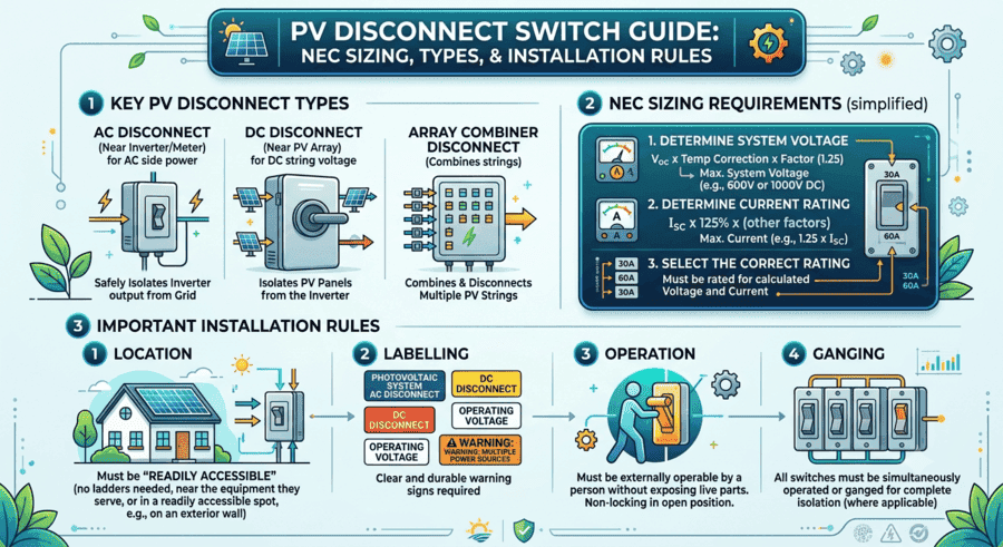
A PV disconnect switch is a manually operated safety device that isolates the direct current flowing from a photovoltaic array to the inverter, letting installers, maintenance crews, and first responders de-energize a solar system for safe servicing. Under NEC Article 690, most residential DC disconnects are sized at 125 percent of the array’s short-circuit current (Isc) with a voltage rating that exceeds the array’s maximum open-circuit voltage (Voc). The switch must be readily accessible, capable of being locked in the open position, and listed to UL 98B for PV service. Every solar permit set needs a documented disconnect location, rating, and label schedule before an AHJ will approve it.
This guide covers what a PV disconnect switch is, how it differs from an AC disconnect and a utility disconnect, how to size one with the NEC formula, where it has to be installed, and the plan review mistakes that most often send a permit back for correction. Disconnect documentation is one piece of a much larger plan set, and understanding the full set of solar permit requirements helps installers avoid an entire revision cycle.
PV Disconnect Switch: Quick Reference
| Attribute | Typical Residential | Typical Commercial |
| DC voltage rating | 600V to 1000V | 1000V to 1500V |
| Current rating (min.) | Isc x 1.25 | Isc x 1.25, often multi-string |
| Governing NEC sections | 690.13, 690.15, 690.8 | 690.13, 690.15, 705.12 |
| Listing standard | UL 98B (PV switches) | UL 98B or UL 98 with PV rating |
| Mounting location | Within sight of inverter, max. 10 ft, or lockable if farther | Same rule, often multiple disconnects per inverter bank |
| Typical cost | $75 to $450 | $300 to $1,500+ |
What Is a PV Disconnect Switch?
A PV disconnect switch, sometimes called a DC disconnect or PV isolator switch, is an electrical safety device installed in the direct current side of a solar array. Its job is to interrupt the flow of DC power between the modules and the inverter so the circuit can be worked on without live voltage present. Unlike a household light switch, a PV disconnect has to safely break DC current, which does not naturally cross zero the way AC current does 120 times per second, so it needs specialized contact materials and arc-quenching design to extinguish the arc that forms when the circuit opens under load.
Every grid-tied and most off-grid PV systems in the United States require at least one DC disconnect and, on the inverter’s output side, an AC disconnect. NEC 690.13 sets the baseline requirement for a disconnecting means ahead of any energized PV equipment, and NEC 690.15 covers the disconnecting means for the array itself, including where a disconnect can be integrated into other equipment such as a combiner box or a power center.
Why Every Solar PV System Needs a Disconnect Switch
A disconnect switch is the mechanism that lets a person physically separate a solar array from the rest of the electrical system on demand. Without one, the only way to de-energize a string of modules is to wait for darkness, which is not an option during a fire, a fault, or scheduled maintenance. Both the NEC and OSHA 29 CFR 1910.303(f) require that disconnecting means be legibly marked and capable of being locked in the open position, which is what makes lockout and tagout procedures possible on a live PV circuit.
- Emergency shutdown: firefighters and first responders need a fast, obvious way to isolate the array before ventilating a roof or entering a structure.
- Maintenance safety: technicians can de-energize a string or the whole array before opening enclosures, replacing components, or troubleshooting a fault.
- Code compliance: AHJ reviewers check disconnect location, rating, and labeling on nearly every residential and commercial plan set.
- Grid isolation: the AC disconnect allows the system to be separated from the utility grid independently of the DC side, which is required for utility line work.
Solar Permit Solutions
Skip the Permit Headaches
We design plan sets that pass inspection the first time. Code-compliant, PE-stamped, accepted by AHJs nationwide.
PV Disconnect vs. AC Disconnect vs. Utility Disconnect
These three terms get used interchangeably on job sites, but each one refers to a different device with a different code basis and a different reviewer checking it.
| Device | Location | Current Type | Primary Code Section |
| PV (DC) disconnect | Between array and inverter | DC | NEC 690.13, 690.15 |
| AC disconnect | Between inverter and utility meter | AC | NEC 690.54, 705.10 |
| Utility disconnect | At or near the utility meter, accessible to utility personnel | AC | Utility interconnection tariff plus NEC 705 |
The DC disconnect and the AC disconnect are both required on essentially every grid-tied residential system. The utility disconnect is a separate, sometimes redundant, requirement that specific utilities add through their interconnection agreement process, most commonly a lockable, utility-accessible AC disconnect located outdoors within a set distance of the utility meter. Some utilities accept the inverter’s integrated AC disconnect as satisfying this requirement; others require a dedicated, separately labeled switch. Confirming which applies is part of the interconnection application, not the building permit.
How a PV Disconnect Switch Works
Mechanically, a PV disconnect is a manually operated, non-fused or fused switch that opens all ungrounded conductors of the circuit simultaneously. Rotary DC disconnects use a rotating blade mechanism with a quarter-turn handle; they are the most common style on residential rooftops because they combine a compact enclosure with a clear visual indication of open or closed position. Load-break rated switches are designed to be safely operated while current is flowing, using spring-loaded quick-break mechanisms and arc chutes or magnetic blowout coils to extinguish the arc; non-load-break switches must only be opened after the circuit has already been de-energized by other means, and using one under load can weld the contacts or start a fire.
Because DC arcs sustain themselves longer than AC arcs, disconnect switches rated for PV service use contact materials such as silver-tungsten alloys along with dedicated arc-quenching chambers. This is why a standard AC disconnect switch cannot simply be relabeled for DC service. Equipment intended for PV DC circuits has to carry a listing that specifically covers that use case.
Types of PV Disconnect Switches
DC Disconnect Switches
Installed between the array (or combiner box) and the inverter, DC disconnects handle the highest voltages in the system, up to 1000V on most residential strings and up to 1500V on commercial arrays. Common configurations include 2-pole units for a single string, 4-pole and 6-pole units for multiple strings sharing one enclosure, voltage ratings of 600V, 1000V, and 1500V, and enclosure ratings of NEMA 3R or better for outdoor use. For a full walkthrough of how string configuration and disconnect placement show up on the required design document, see our solar wiring diagram guide.
AC Disconnect Switches
Installed between the inverter and the point of utility interconnection, AC disconnects are mechanically simpler to design because alternating current crosses zero 120 times a second, which makes arc interruption far less demanding than on the DC side. AC disconnects still need to be readily accessible, weatherproof, and clearly labeled, and their placement relative to the main panel matters for the 120 percent busbar rule on load-side interconnections.
Integrated and Combination Disconnects
Many modern string inverters ship with an integrated DC disconnect built into the enclosure, and some power centers combine a disconnect, an overcurrent device, and monitoring hardware in a single listed assembly. AHJs generally accept an integrated disconnect as satisfying NEC 690.15 provided it is clearly identified, but some jurisdictions still want a separate, external disconnect documented on the plan set for module-level or string-level isolation, especially on commercial systems with multiple inverters.
How to Size a PV Disconnect Switch (NEC Formula)
Sizing a DC disconnect comes down to two numbers pulled directly from the module datasheet: short-circuit current (Isc) and open-circuit voltage (Voc). NEC 690.8 requires the continuous current rating to account for a safety margin above the array’s calculated maximum current, and the switch’s voltage rating has to exceed the array’s maximum system voltage as calculated under NEC 690.7, which adjusts Voc for the lowest expected ambient temperature at the site.
Minimum Current Rating = Array Isc × 1.25
Minimum Voltage Rating = Array Voc (temperature-corrected) × 1.25 safety margin, or per the site’s calculated maximum voltage
Residential Example: 10 kW String Inverter System
- Array short-circuit current (Isc): 11.5A per string, two strings combined at the combiner = 23A
- Required current rating: 23A x 1.25 = 28.75A, round up to a 32A switch
- Array open-circuit voltage (Voc), temperature-corrected: 435V
- Required voltage rating: select a 600V-rated switch for margin, though many installers standardize on 1000V-rated hardware across all residential jobs
Commercial Example: 75 kW Multi-String System
- Combined array Isc across all strings feeding one combiner: 96A
- Required current rating: 96A x 1.25 = 120A, round up to a 125A disconnect
- Temperature-corrected Voc: 890V
- Required voltage rating: 1000V minimum; many commercial designs standardize on 1500V-rated switches to support future array expansion
Always round up to the next standard switch rating rather than down, and never use the main breaker’s rating in place of the array’s calculated current when sizing a disconnect. Reviewers checking the 120 percent busbar rule on the AC side look specifically at the panel’s busbar rating from its own datasheet, not the main breaker size, and the same discipline applies on the DC side: size to the array’s actual output, not to a convenient round number.
NEC Code Requirements for PV Disconnect Switches
Article 690 of the National Electrical Code is the primary source governing PV disconnects, with several other articles layered on top depending on system configuration. Our NEC 2023 Article 690 updates guide covers the full set of changes; the sections most relevant to disconnect switches specifically are summarized below.
| NEC Section | What It Covers |
| 690.8 | Maximum circuit current calculations that drive disconnect current rating |
| 690.13 | General requirement for a disconnecting means ahead of PV system equipment |
| 690.15 | Disconnecting means for PV system equipment, including where an integrated disconnect is acceptable |
| 690.12 | Rapid shutdown, which interacts with disconnect placement and labeling |
| 690.31(G)(4) | DC conduit and box labeling along the run between the array and the disconnect |
| 705.12 | Interconnection rules, including the 120 percent busbar rule for AC disconnect placement |
| 705.10 | Power source directory and multiple-power-source labeling at the service equipment |
Equipment listing matters as much as the code section. PV disconnect switches sold for DC service should carry a UL 98B listing, the outline of investigation specifically written for enclosed and dead-front switches used in photovoltaic systems, layered on top of the base UL 98 switch standard. UL Solutions evaluates PV disconnects separately from general-purpose switches precisely because DC arc interruption requires different testing than AC switching. A disconnect that only carries a UL 98 listing without the 98B supplement has not been evaluated for PV DC service and should not be specified on a solar plan set.
Where a PV Disconnect Has to Be Installed
Placement rules exist to make sure a disconnect can actually be found and operated in an emergency. NEC 690.15 and the general accessibility requirements for electrical disconnecting both point toward the same principle: the disconnect has to be visible, reachable, and marked clearly enough that someone unfamiliar with the specific installation can still find and operate it.
- DC disconnects should be within sight of the inverter, generally interpreted as within 10 feet with a clear line of sight, unless the switch is capable of being locked in the open position, in which case greater separation is allowed.
- AC disconnects need to be readily accessible to both the homeowner or facility operator and to utility personnel, and outdoor placement near the meter is standard on most residential jobs.
- Operating handles should sit no higher than 6.5 feet above the working surface, per the general accessibility provisions carried into 29 CFR Part 1910 Subpart S.
- A minimum of 3 feet of clear working space is required in front of any disconnect, matching the general working-space rule for electrical equipment.
- Disconnecting means the machine must be capable of accepting a lock in the open position, which is what makes lockout and tagout procedures possible during maintenance.
Every disconnect location, along with its rating and the conductor labeling that runs to it, needs to appear on the electrical single-line diagram, not just in a spec sheet buried elsewhere in the plan set. Reviewers trace the circuit from the array to the point of interconnection on the SLD, and a disconnect that exists in the field but is missing from the diagram is a common source of plan check comments.
PV Disconnect Labeling Requirements
Labeling ties directly into disconnect placement, and it is one of the most frequently cited items in field inspections. Every disconnecting means must be legibly marked to indicate its purpose, and the marking has to be durable enough to withstand the outdoor environment the switch is installed in. For the complete set of required PV label locations, exact wording, and color rules across NEC editions, see our solar PV labeling requirements guide. A few points specific to disconnect switches:
- The DC disconnect needs an electrical data label showing maximum DC voltage per NEC 690.7(D) in the 2023 NEC or the older 690.53 wording in jurisdictions still on the 2017 or 2020 edition.
- The AC disconnect needs a label identifying it as the PV system disconnect, with a cross-reference to the DC disconnect location where the two are separated.
- A backfed breaker on a load-side interconnection needs a WARNING: BACKFED BREAKER label in addition to the disconnect marking.
- Label color and contrast requirements are set out in standards such as ANSI Z535, which governs safety sign and label design, including signal words, color coding, and minimum text height for hazard warnings.
The rapid shutdown initiation device carries its own separate labeling requirement under NEC 690.12(D)(2). If the disconnect also functions as, or sits near, the rapid shutdown switch, both labels need to be present and correctly worded. Our rapid shutdown compliance roadmap and our guide to the NEC 690.56(C) and 690.12(D) label wording cover the exact text required and how it changed between code editions.
PV Disconnects on Commercial and Multi-Inverter Systems
Commercial arrays typically use multiple string inverters or a central inverter feeding several combiner circuits, which usually means multiple DC disconnects instead of a single switch. For a broader look at how commercial system architecture affects the electrical design, see our guide to commercial solar PV systems. Most jurisdictions require both electrical and structural plans on commercial projects to carry a PE stamp from an engineer licensed in the project’s state, and disconnect sizing calculations are typically part of what the engineer reviews before stamping the plan set.
The 2023 NEC also added a specific exception for non-enclosed detached structures, meaning carports, canopies, and solar trellises that are not enclosed are exempt from the rapid shutdown requirement under NEC 690.12 Exception No. 2. That exception affects labeling and switch placement on canopy-mounted commercial arrays; see our guide to the NEC 2023 rapid shutdown exemptions for which structures qualify, since not every AHJ applies the exception the same way.
PV Disconnect Requirements With Battery Storage
Adding battery storage to a PV system introduces additional disconnecting means beyond the standard array and AC disconnects. NEC Article 706 governs energy storage systems and requires their own disconnect, sized and rated separately from the PV disconnect, along with disconnects for any DC-coupled or AC-coupled connection between the battery and the rest of the system. A PV-only disconnect schedule from an existing plan set does not cover a battery retrofit; our solar battery permit requirements guide walks through what changes when storage is added, including the additional disconnect, labeling, and fire code documentation an AHJ will expect.
Common AHJ Plan Review Mistakes on PV Disconnects
Disconnect-related corrections are among the most frequent and most avoidable reasons a plan set gets sent back. Reviewers checking a submission against their jurisdiction’s requirements, similar to how any AHJ evaluates a solar permit application, tend to flag the same handful of issues repeatedly.
| Common Rejection Reason | How to Prevent It |
| Disconnect sized off the main breaker instead of the array’s calculated Isc and Voc. | Show the Isc x 1.25 and Voc calculations explicitly on the plan set, referencing the module datasheet. |
| Switch not listed for PV DC service (UL 98 only, no 98B supplement) | Specify equipment with a UL 98B listing on the bill of materials and confirm the datasheet shows it. |
| Disconnect location missing from the single-line diagram | Show every disconnect, its rating, and its physical location on the SLD, not just in a spec table |
| Missing or incorrect voltage or power source labeling at the disconnect | Include a dedicated label schedule with exact wording, not a generic note referencing NEC 690 |
| The AC disconnect location does not satisfy the utility’s accessibility requirements. | Confirm the specific utility’s interconnection technical requirements before finalizing placement. |
| Disconnect not shown as capable of being locked in the open position | Specify a lockable handle and note the lockout capability on the equipment schedule. |
Installation Best Practices
- Calculate Isc and Voc from the actual module datasheet, not a generic assumption, and apply the 125 percent factor to both.
- Select equipment listed to UL 98B for the DC side and confirm the enclosure rating (NEMA 3R or better) matches the installation environment.
- Mount the DC disconnect within sight of the inverter, or specify a lockable switch if greater separation is unavoidable.
- Keep the operating handle at or below 6.5 feet and maintain at least 3 feet of clear working space in front of the enclosure.
- Document every disconnect location, rating, and label on the single-line diagram before submission, not after a redline comes back.
- Cross-check the AC disconnect placement against the specific serving utility’s interconnection technical requirements, which sometimes exceed the NEC baseline.
- Confirm anti-islanding and grid-support functionality of the inverter meets IEEE 1547 if the utility’s interconnection application asks for it, since this affects how the AC disconnect interacts with the grid.
Disconnect Documentation and Streamlined Permitting
Jurisdictions that use the Department of Energy’s SolarAPP+ platform run an automated code compliance check before issuing a permit, and disconnect data fields are part of what the tool validates. Incomplete or inconsistent disconnect information, a rating on the SLD that does not match the equipment datasheet, or a missing UL listing, will fail the automated check the same way it would trigger a manual redline. According to NREL’s soft cost research, permitting and inspection remain a meaningful share of total residential solar soft costs, which is one reason accurate, complete disconnect documentation on the first submission matters as much for project economics as it does for code compliance. Databases like DSIRE and direct contact with the local building department remain the most reliable way to confirm which disconnect requirements apply before design begins.
Fire Code Considerations for Disconnect Access
Beyond the NEC, the International Fire Code adds requirements that affect disconnect visibility and access, particularly reflectivity and placement relative to firefighter access pathways on rooftop systems. Local jurisdictions that have adopted the IFC independently of their NEC cycle may apply additional conduit marking intervals or clearance rules around the disconnect location, so confirming the locally adopted fire code edition matters as much as confirming the NEC edition when finalizing disconnect placement on a rooftop array.
Get Disconnect Sizing and Placement Right the First Time
PV disconnect switches sit at the intersection of NEC code compliance, equipment listing, and physical accessibility, and a mistake in any one of those three areas is enough to trigger a plan check correction. The installers who consistently earn first-pass approval calculate disconnect ratings from actual module data, specify UL 98B-listed equipment, and document every disconnect location and label on the single-line diagram before the plan set is ever submitted.
Solar Permit Solutions produces PE-stamped, AHJ-ready plan sets for residential and commercial solar projects across all 50 states, with disconnect sizing, placement, and labeling documented to match each jurisdiction’s adopted code edition. Create a free account at solarpermitsolutions.com to get started, or explore the blog library for more technical guidance on solar permitting and NEC compliance.
Frequently Asked Questions About PV Disconnect Switches
Skip the Permit Headaches
We design plan sets that pass inspection the first time. Code-compliant, PE-stamped, accepted by AHJs nationwide.
Frequently Asked Questions
They refer to the same device. "PV disconnect" is the engineering term used in NEC Article 690 and by equipment manufacturers, while "solar disconnect" is the more common consumer-facing term. Both describe the switch that isolates the array's DC output from the rest of the system.
Yes, for virtually every grid-tied residential and commercial system. The DC disconnect isolates the array from the inverter, and the AC disconnect isolates the inverter's output from the utility grid. Some inverters integrate the DC disconnect into their enclosure, but a separate AC disconnect near the point of interconnection is still required in most jurisdictions.
Multiply the array's short-circuit current (Isc) by 1.25 to get the minimum current rating, and select a voltage rating that exceeds the array's temperature-corrected open-circuit voltage (Voc). Round up to the next standard switch size rather than down, and confirm the equipment carries a UL 98B listing for PV DC service.
No. DC arcs do not self-extinguish the way AC arcs do, so a disconnect intended for PV DC service needs specialized contact materials and arc-quenching design. Equipment should carry a UL 98B listing, which specifically evaluates switches for photovoltaic DC circuits, not a general UL 98 listing alone.
The DC disconnect should be within sight of the inverter, generally interpreted as within 10 feet with a clear line of sight, unless it is capable of being locked in the open position. The AC disconnect needs to be readily accessible to the system owner and to utility personnel, typically mounted outdoors near the utility meter.
Yes. Disconnecting means covered under this subpart must be capable of being locked in the open position, which is what enables lockout and tagout procedures during maintenance or emergency shutdown.
No, though they are often located near each other. A PV disconnect isolates the array from the inverter or the inverter from the grid. A rapid shutdown initiation device triggers a system-wide voltage reduction under NEC 690.12 and carries its own separate labeling requirement.
An undersized disconnect, or one sized off the main breaker rating instead of the array's actual Isc and Voc, is a common and immediate cause of plan check corrections. AHJ reviewers check the calculation against the module datasheet, and a mismatch typically triggers a full resubmission cycle.
Yes. NEC Article 706 requires energy storage systems to have their own disconnecting means, sized and rated independently from the PV array disconnect. A PV-only disconnect schedule does not cover the additional circuits a battery retrofit introduces.
PV disconnect switches should carry a UL 98B listing, the outline of investigation written specifically for enclosed and dead-front switches used in photovoltaic systems, in addition to meeting the base UL 98 switch standard. A switch listed only to UL 98 has not been evaluated for DC PV service.

SPS Editorial Team
Solar Permit Solutions
Solar Permit Solutions provides professional solar permit design services for residential, commercial, and off-grid installations across all 50 states. Our team ensures permit-ready plan sets delivered fast.
Related Articles
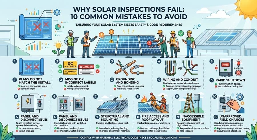
Why Solar Inspections Fail: 10 Common Mistakes to Avoid
Discover the 9 critical reasons solar inspections fail and how to avoid costly m...

Solar Grounding And Bonding: How To Pass Inspection Every Time
Learn how to pass solar grounding and bonding inspections every time. Avoid comm...
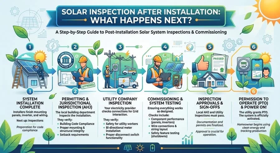
Solar Inspection After Installation: What Happens Next?
Learn how to pass your solar inspection by following essential tips for obtainin...