Understanding electrical panel types is critical when planning solar installation and battery backup integration for your home or business. The right panel configuration determines how efficiently you can connect solar equipment, ensure NEC compliance, and maintain reliable backup power during grid outages. This comprehensive guide covers the four main electrical panel types used in US solar installations, with detailed instructions for connecting Schneider Electric battery backup systems to each configuration.
Key Takeaways:
- Main breaker panels offer the most flexibility for solar interconnection with built-in overcurrent protection
- MLO panels require careful load calculations and specific interconnection methods for solar and backup systems
- Solar-ready load centers like Schneider’s QO Smart Panel simplify installation with integrated energy management
- Commercial panels demand specialized equipment and engineering for high-capacity backup systems
- Schneider Electric Conext XW series inverters provide versatile solutions for all panel types
Understanding US Electrical Panel Types for Solar Applications
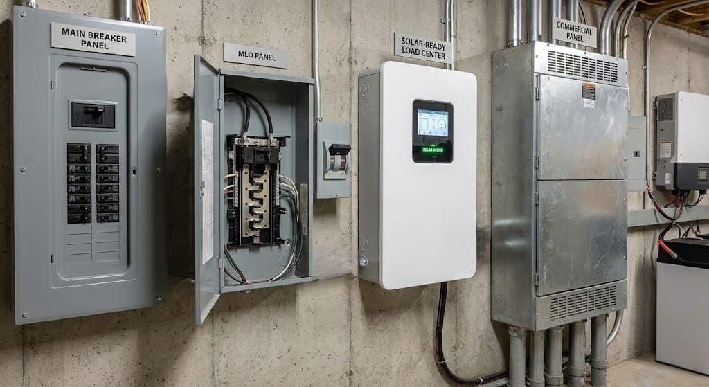
The National Electrical Code recognizes four primary electrical panel configurations for residential and commercial applications. Each panel type presents unique advantages and challenges when integrating solar photovoltaic systems and battery backup solutions. Proper panel selection impacts installation costs, system capacity, code compliance, and long-term reliability.

Why Panel Type Matters for Solar and Backup Power
Your electrical panel serves as the central distribution point for all power in your building. When adding solar and battery backup, the panel must safely handle bidirectional power flow, accommodate additional circuit breakers, and maintain proper overcurrent protection. The wrong panel configuration can limit your solar capacity, require expensive upgrades, or create code compliance issues. For homeowners just getting started, our guide to solar permits in the US provides essential foundational knowledge.
Modern solar installations often combine grid-tied operation with battery backup capability, creating complex system architectures that demand careful panel selection. Schneider Electric manufactures equipment specifically designed to address these challenges across all four panel types. According to research from the National Renewable Energy Laboratory, proper system design significantly impacts long-term performance and reliability.
The Four Main US Electrical Panel Types for Solar
1. Main Breaker Panels (Most Common for Residential)
Main breaker panels represent the most prevalent configuration in US homes and small commercial buildings. These panels feature a large main circuit breaker at the top that controls power to the entire busbar below. This main breaker acts as the primary overcurrent protection device and provides a convenient single disconnect point for the entire electrical system.
Key Characteristics:
- Main breaker ratings: typically 100A, 125A, 150A, or 200A for residential
- Busbar rating: matches or exceeds main breaker rating
- Branch circuit spaces: 20 to 42 circuits depending on panel size
- Built-in overcurrent protection for entire panel
- Suitable for service entrance or as large subpanels
Advantages for Solar Integration: Main breaker panels offer maximum flexibility for solar interconnection. The presence of a main breaker enables use of the 120% rule under NEC 705.12(B)(3)(b), allowing solar backfeed breakers up to 20% of the busbar rating when properly positioned. This configuration simplifies calculations and provides clear protection for both utility and solar power sources. Understanding solar single line diagrams helps ensure proper system design.
Schneider Electric Options:
- QO Load Centers: 100A to 225A main breaker panels with solar-ready features
- QO Smart Panel: Advanced load center with integrated energy monitoring and control
- Square D Energy Center: Purpose-built smart panel for solar and backup integration
- Homeline Load Centers: Cost-effective solution for residential applications
How to Connect Battery Backup to Main Breaker Panels Using Schneider Electric
Schneider Electric’s Conext XW and XW Pro series inverter/chargers provide comprehensive backup power solutions for main breaker panels. These hybrid inverters combine grid-tied solar operation with seamless battery backup during outages.
System Components Required:
- Schneider Conext XW Pro 6848 or XW 6048 inverter/charger (6 kW continuous output)
- Schneider Power Distribution Panel (PDP) with appropriate breakers
- Battery bank: 48V DC, minimum 440Ah capacity recommended
- Battery temperature sensor (included with Conext systems)
- Conext System Control Panel for monitoring and configuration
- Proper DC and AC disconnect switches per NEC requirements
System Architecture:
The Conext XW system creates a sophisticated power management architecture that seamlessly transitions between grid power, solar generation, and battery backup. The inverter/charger connects to your main panel through the Power Distribution Panel, which houses all necessary circuit breakers and transfer switches.

Installation Steps:
- Location Planning: Install the Conext XW inverter/charger within 10 feet of the battery bank to minimize DC cable runs. Mount in a dry, ventilated indoor location away from flammable materials. Maintain minimum clearances of 6 inches on the sides and 12 inches on the front for ventilation.
- Battery Bank Installation: Connect the 48V battery bank using appropriately sized cables. For the XW Pro 6848, use a minimum 4/0 AWG copper cable for runs under 5 feet. Install a 250A DC disconnect breaker between batteries and inverter per NEC Article 706 requirements.
- Power Distribution Panel Wiring: Mount the Schneider PDP adjacent to the Conext XW inverter. This panel contains:
- AC1 input (60A 2-pole breaker): connects to utility through main panel
- AC2 input (30A 2-pole breaker): optional generator connection
- AC output (60A 2-pole breaker): feeds critical loads subpanel
- Bypass breaker: allows maintenance without system shutdown
- Main Panel Interconnection: Install a 60A 2-pole breaker in your main panel to feed the AC1 input of the PDP. This breaker should be positioned at the opposite end from the main breaker if using the load-side interconnection method. Run appropriately sized conductors (typically 6 AWG copper for a 60A circuit).
- Critical Loads Subpanel: Install a subpanel near the PDP to distribute backup power to essential circuits. Transfer critical circuits from your main panel to this backup subpanel. Size the subpanel based on total critical load requirements, typically 60A to 100A for residential applications.
- System Configuration: Connect the Conext System Control Panel via the Xanbus network. Configure battery type, charging parameters, grid support settings, and backup operation mode through the intuitive menu system.
How It Works:
Normal Operation (Grid Available):
- Utility power flows through AC1 input to power the home
- Solar charge controllers (if installed) charge batteries from PV array
- Excess solar energy exports to grid if net metering enabled
- The inverter maintains batteries at optimal charge level
- All loads operate normally from grid and solar
During Grid Outage:
- Conext XW detects utility failure within 16 milliseconds
- Internal automatic transfer switches disconnect from the grid
- The inverter begins powering critical loads from batteries and solar
- Non-critical loads in main panel lose power
- Automatic Generator Start (AGS) can engage backup generator if configured
- The system operates in off-grid mode, maintaining stable 120/240V output
When Grid Returns:
- The inverter monitors grid quality for proper voltage and frequency
- After 5-minute stabilization period, automatic reconnection occurs
- Transfer switches close, restoring grid connection
- Batteries begin recharging if depleted during an outage
- The system returns to normal grid-interactive operation
- All critical and non-critical loads powered normally
Advanced Features:
The Schneider Conext XW Pro includes sophisticated power management capabilities that optimize backup operation. Grid support mode enables frequency and voltage regulation to support utility during peak demand. The system can perform load shedding automatically when battery capacity runs low, prioritizing the most critical circuits. AC coupling capability allows integration with existing grid-tied solar inverters, adding backup functionality to systems without battery support.
NEC Compliance Considerations:
Installation must comply with NEC Articles 690 (Solar PV Systems), 705 (Interconnected Power Sources), 706 (Energy Storage Systems), and 702 (Optional Standby Systems). All disconnects must be clearly labeled. Arc-fault and ground-fault protection are required per 2023 NEC updates. Battery installation must meet ventilation and spacing requirements of Article 706.10. For a deeper understanding of AHJ solar requirements, consult local authorities having jurisdiction.
2. Main Lug Only (MLO) Panels
Main Lug Only panels lack a main circuit breaker and instead feature lugs that connect directly to incoming feeder conductors. These panels serve as distribution points downstream from overcurrent protection located in an upstream panel or meter-main combination. MLO panels are commonly used as subpanels in residential applications and as secondary distribution points in commercial installations.
Key Characteristics:
- No main breaker within the panel enclosure
- Rated typically from 100A to 400A
- Rely on upstream overcurrent protection device
- Lower cost than equivalent main breaker panels
- Cannot serve as service entrance equipment without modification
Considerations for Solar Integration: MLO panels present unique challenges for solar interconnection. The absence of a main breaker complicates application of the 120% rule, as the panel’s capacity is limited by both the upstream feeder breaker and the panel’s own busbar rating. Many jurisdictions prohibit backfeed breakers in MLO panels without first installing a main breaker, though some permit supply-side taps or require careful load-side calculations. Avoiding common solar permit design mistakes is essential for approval.
Schneider Electric Options:
- QO MLO Load Centers: 100A to 225A configurations
- Homeline MLO panels: Economical residential distribution
- NQ Panelboards: Commercial-grade MLO distribution panels
How to Connect Battery Backup to MLO Panels Using Schneider Electric
Connecting battery backup to MLO panels requires careful planning to maintain proper overcurrent protection and NEC compliance. The approach differs significantly from main breaker panel installations.
System Components Required:
- Schneider Conext XW Pro 6848 inverter/charger
- Schneider Power Distribution Panel
- Battery bank: 48V DC, 440 Ah minimum capacity
- Main breaker retrofit kit (if converting MLO to main breaker configuration)
- All standard Conext accessories and monitoring equipment
System Architecture:
For MLO panels, the most code-compliant approach involves one of three methods: converting the MLO panel to a main breaker configuration, using a supply-side connection before the panel, or carefully calculating load-side interconnection with the upstream breaker serving as the main overcurrent protection device.

Installation Methods:
Method 1: MLO to Main Breaker Conversion (Recommended)
- Panel Assessment: Verify the MLO panel is convertible to the main breaker configuration. Most Schneider QO and Homeline load centers include convertible mains capability.
- Main Breaker Installation: Install an appropriately rated main breaker kit in the MLO panel. Select breaker rating based on upstream feeder capacity and panel busbar rating. For a 200A panel fed by a 200A upstream breaker, install a 200A main breaker.
- System Connection: With the main breaker installed, proceed with the battery backup connection identical to the main breaker panel method described above. Install PDP feeder breaker at opposite end of busbar from new main breaker per 120% rule.
- Verification: Ensure the upstream breaker and the new main breaker are properly coordinated. Label all disconnects clearly per NEC 705.12(B)(3).
Method 2: Supply-Side Tap Connection
- Tap Location: Install a junction box on the line side (supply side) of the MLO panel’s lugs. This tap point must be accessible and properly rated for the feeder conductor size.
- Conext Connection: Run conductors from the junction box to the Conext PDP AC1 input. Size conductors based on inverter output current and distance. For the XW Pro 6848, use minimum 6 AWG copper for circuits under 50 feet.
- Overcurrent Protection: Install appropriately sized fused disconnect or circuit breaker between tap point and inverter. This provides required overcurrent protection for the tap conductors.
- AHJ Approval: Many jurisdictions require prior approval for supply-side taps. Submit electrical plans showing tap location, conductor sizing, and overcurrent protection before installation.
Method 3: Load-Side with Upstream Protection
- Load Calculation: Calculate total connected load in MLO panel and verify against upstream breaker rating. Document that upstream breaker can handle combined load and backfeed current.
- Breaker Positioning: If using load-side connection, install backfeed breaker in MLO panel at opposite end from incoming lugs. This creates maximum separation between power sources.
- Current Limits: Total current from backfeed breaker plus upstream feeder breaker must not exceed panel busbar rating or feeder conductor capacity. For example, with 200A panel and 200A upstream breaker, backfeed breaker is limited to 0A unless upstream breaker is downsized.
- Documentation: Provide detailed calculations to AHJ showing compliance with NEC 705.12(B) requirements. Some jurisdictions may reject this method entirely for MLO panels.
How It Works:
The operational sequence for MLO panel backup systems matches main breaker panel operation, with the critical distinction that the upstream breaker serves as the main disconnect. During grid outages, the Conext XW system isolates from both the utility and the MLO panel, powering only the critical loads subpanel.
Normal Operation:
- Grid power flows through upstream breaker to MLO panel
- MLO panel distributes power to all connected loads
- Conext XW charges batteries from AC1 input
- Critical loads subpanel receives power through Conext AC output
- Solar charging occurs if PV array and charge controllers installed
During Grid Outage:
- Loss of utility power detected at upstream service point
- Conext XW disconnects from grid on AC1 input
- Inverter powers critical loads subpanel from batteries
- Main MLO panel loads lose power (no utility source)
- Off-grid operation continues until grid restoration or battery depletion
When Grid Returns:
- Utility voltage detected on AC1 input
- 5-minute stabilization and grid qualification period
- Automatic reconnection to grid
- Battery recharging commences
- Normal operation resumes
Special Considerations for MLO Backup Systems:
MLO panel backup installations require more extensive AHJ coordination than main breaker panel installations. Installers must clearly demonstrate code compliance with multiple NEC articles. The supply-side tap method offers the most straightforward code compliance but requires utility coordination for temporary service interruption during installation. Converting MLO to main breaker configuration often provides the best long-term solution, enabling simpler future solar expansions or system upgrades. Understanding solar permit timelines helps with project planning.
3. Solar-Ready Load Centers
Solar-ready load centers represent purpose-built solutions designed specifically for photovoltaic integration and energy storage systems. These advanced panels incorporate features that simplify solar interconnection, facilitate battery backup integration, and enable comprehensive energy management. Schneider Electric leads the industry with its QO Smart Panel and Energy Center products.
Key Characteristics:
- Pre-engineered for solar and storage integration
- Built-in energy monitoring capabilities
- Smart breakers with remote control and load management
- Integrated surge protection for solar equipment
- Compliant with latest NEC energy storage requirements
- Designed for plug-and-play battery backup connection
Advantages for Solar Integration: Solar-ready panels eliminate many common installation challenges. Pre-installed monitoring hardware tracks energy production and consumption at the circuit level. Smart relays enable automatic load shedding during backup operation, maximizing battery runtime. Dedicated solar breaker positions ensure proper spacing for backfeed breakers. Many include integrated disconnect switches that simplify compliance with NEC rapid shutdown requirements.
Schneider Electric Options:
- Square D Energy Center Smart Panel: Features split-bus interior, integrated 20A GFCI outlet, and solar- and backup-power-ready design. Compatible with QO 3/4-inch circuit breakers.
- QO Smart Panel System: Includes QO PoN (Plug-on Neutral) load center, Schneider Energy Monitor, QO Smart Relays for circuit-level control, and Schneider Home app for monitoring.
- QO Solar-Ready Load Centers: 12-space and larger QO panels with solar-ready features, convertible mains, and smart panel functionality.
How to Connect Battery Backup to Solar-Ready Panels Using Schneider Electric
Schneider’s solar-ready panels streamline battery backup integration through intelligent system architecture and pre-engineered components. The QO Smart Panel with Schneider Pulse power control system represents the cutting edge of residential energy management.
System Components Required:
- Schneider QO Smart Panel (PoN configuration)
- Schneider Energy Monitor (installed in panel)
- QO Smart Relays (2-8 relays for critical circuit control)
- Schneider Conext XW Pro inverter/charger
- Battery bank: 48V system, appropriately sized for backup duration
- Schneider Home app for system monitoring and control
- Optional: Schneider Pulse advanced power control system
System Architecture:
The solar-ready panel architecture integrates five key subsystems: the QO Smart Panel with main breaker and circuit distribution, the energy monitoring system tracking all power flows, smart relays controlling individual circuits, the Conext battery backup inverter, and the Schneider Home app providing user interface and system optimization. For DIY enthusiasts, residential solar permit services offer step-by-step guidance.

Installation Steps:
- Smart Panel Installation: Mount the QO Smart Panel at the service entrance location. The PoN design simplifies branch circuit wiring by eliminating separate neutral pigtails for AFCI and GFCI breakers.
- Energy Monitor Integration: Install the Schneider Energy Monitor on the main lugs of the QO panel. This monitor consists of current transformers on each line conductor and a communication module. The monitor tracks total consumption, solar production, battery status, and grid interaction in real time.
- Smart Relay Placement: Install QO Smart Relays in breaker positions for circuits requiring backup power or load management. Each smart relay controls one double-pole or two single-pole circuits. Relays communicate wirelessly with the Energy Monitor and support remote on/off control.
- Critical Loads Configuration: Wire essential circuits through smart relays, including:
- Refrigerator and freezer circuits
- Well pump or sump pump
- Heating system circulator pumps
- Essential lighting circuits
- Communication equipment (internet router, phones)
- Medical equipment, if applicable
- Conext XW Integration: Connect the Conext XW Pro system to the QO Smart Panel using the standard PDP interconnection method. The AC1 input receives power from a breaker in the smart panel. Configure the inverter to communicate with the energy monitor via Modbus protocol if available, or operate as a standalone backup system.
- Schneider Home App Setup: Download the Schneider Home app and connect to the Energy Monitor via WiFi. Configure circuit names, set priorities for backup operation, establish load shedding sequences, and monitor system performance.
Advanced Power Management with Schneider Pulse:
For maximum backup optimization, integrate the Schneider Pulse Power Control System. This advanced controller coordinates battery storage, solar production, and load management using sophisticated algorithms that extend backup runtime and maximize solar self-consumption.
How It Works:
Normal Operation (Grid Available):
- Utility power flows through main breaker to the busbar
- The energy monitor tracks all power flows continuously
- Solar production (if installed) powers loads and charges batteries
- Smart relays remain closed, all circuits operational
- Schneider Home app displays real-time energy data
- Excess solar exports to grid through net metering
- The battery maintains float charge for backup readiness
During Grid Outage:
- The energy monitor detects utility failure instantly
- Signal sent to Conext XW inverter to begin backup operation
- The inverter disconnects from grid and begins island mode
- Smart relays automatically implement load priority scheme
- Non-essential circuits open first (air conditioning, electric vehicle charger)
- Essential circuits remain powered from battery and solar
- The pulse system optimizes load distribution based on available battery capacity
- The user receives notification via Schneider Home app
Battery Management During Outage:
The QO Smart Panel system actively manages power consumption to maximize backup duration. As battery state-of-charge decreases, the system progressively sheds non-critical loads:
100-70% Battery Capacity:
- All critical circuits remain powered
- Solar charging continues if sunlight available
- No load restrictions
70-40% Battery Capacity:
- Convenience loads shed automatically (outlets, non-essential lighting)
- HVAC may cycle or shut down depending on configuration
- Essential circuits maintain full power
- User notified of load reduction
40-20% Battery Capacity:
- Only highest priority circuits remain active
- Refrigerator cycling managed to extend battery life
- Critical loads like medical equipment maintain continuous power
- The system alerts user to low battery status
Below 20% Battery Capacity:
- Emergency mode activated
- Only life-safety circuits remain powered
- The system prepares for orderly shutdown
- Generator auto-start engaged if configured
When Grid Returns:
- The energy monitor confirms stable grid voltage and frequency
- 5-minute grid qualification period prevents reconnection to unstable power
- Smart relays remain open during stabilization
- Conext XW begins battery recharging at maximum safe rate
- After successful grid synchronization, smart relays restore loads sequentially
- Soft-start prevents inrush current surge to the grid
- The system returns to normal monitoring mode
- Battery recharging continues until full capacity reached
Integration with Solar Production:
Solar-ready panels with battery backup create sophisticated microgrids that optimize energy independence. The system prioritizes solar utilization in this order: first, power instantaneous loads; second, charge batteries; third, export excess to the grid. During outages, solar continues charging batteries during daylight hours, substantially extending backup duration.
Energy Management Features:
The Schneider Home app provides unprecedented visibility into home energy patterns. Users can view historical consumption by circuit, compare solar production to usage, track battery health and cycle count, and analyze grid interaction. The system generates reports showing potential savings from increased solar self-consumption and identifies opportunities for load shifting to off-peak hours. Resources like EnergySage help homeowners compare solar options and understand energy costs.
NEC 2023 Compliance:
Solar-ready panels meet the enhanced requirements of NEC 2023 for energy storage systems and optional standby power. The integrated design addresses Article 702.4 capacity requirements through the Power Control System, which ensures battery backup never exceeds safe operating limits. Smart relays provide the required load management capability without manual transfer switches.
Advantages of Solar-Ready Panel Approach:
This integrated approach offers significant benefits over traditional panel/backup combinations. Installation time decreases by 30-40% compared to conventional subpanel transfer systems. The unified monitoring platform eliminates compatibility issues between disparate equipment brands. Future expandability is simplified, as adding circuits to backup protection requires only installing additional smart relays. The system easily integrates electric vehicle charging with intelligent load management, preventing service panel overload. Those considering net metering should understand how solar panels connect to the grid.
4. Commercial and Industrial Panels
Commercial and industrial electrical distribution systems operate at much larger scales than residential installations, with capacities ranging from 400A to several thousand amperes. These systems typically employ panelboards (20-inch-wide commercial panels) or switchboards for main distribution, with multiple downstream panels serving various building areas. Solar and battery backup integration at a commercial scale requires specialized engineering and equipment.
Key Characteristics:
- Main panelboards rated 400A to 1200A typical
- Three-phase power distribution (208V, 480V, or 600V)
- Multiple distribution levels with various panel types
- Complex load requirements and diversity factors
- Extensive monitoring and control systems
- Compliance with commercial building codes and utility requirements
Considerations for Solar Integration: Commercial solar installations often exceed 100 kW and require utility interconnection studies. NEC Article 691 governs large-scale PV installations over 5 MW. Battery energy storage systems for commercial buildings must comply with International Fire Code requirements for thermal runaway protection and fire suppression. Proper engineering analysis ensures solar and backup systems integrate safely with existing emergency power equipment like fire pumps and exit lighting. The Solar Energy Industries Association provides global context for commercial solar adoption trends.
Schneider Electric Options:
- NQ Panelboards: Commercial-grade distribution panels up to 1200A
- Commercial switchboards: Main distribution equipment for large facilities
- Conext XW Pro for smaller commercial applications (up to 36kW in parallel configuration)
- Industrial-grade energy storage systems for larger installations
- PowerLogic energy management systems for comprehensive monitoring
How to Connect Battery Backup to Commercial Panels Using Schneider Electric
Commercial battery backup systems require careful design to meet specific building codes, achieve desired backup duration, and integrate with existing emergency power systems. Schneider Electric provides scalable solutions from small commercial spaces to large industrial facilities.
System Components Required:
- Multiple Schneider Conext XW Pro inverters (3-phase systems require 3 or 6 units)
- Commercial-grade battery bank: 48V lithium-ion recommended for commercial applications
- Master controller for inverter coordination
- Commercial switchgear for isolation and protection
- Building management system integration capability
- Fire alarm and suppression system per IFC requirements
- Extensive monitoring and remote management capability
Design Considerations:
Load Analysis: Conduct comprehensive load study identifying critical circuits requiring backup power. Commercial buildings typically back up:
- Emergency lighting and exit signs
- Fire alarm and suppression systems
- Elevators (one car minimum)
- Critical HVAC for server rooms and refrigeration
- Security and access control systems
- Essential business operations equipment
Battery Sizing: Calculate battery capacity based on critical load profile and desired backup duration. Commercial applications typically target 2-4 hours backup for essential loads. For a 50kW critical load requiring 4-hour backup: 50kW × 4h = 200kWh battery capacity required. Add a 20% margin for aging and efficiency losses.
Electrical Distribution Design: Develop a single-line diagram showing:
- Main utility service and protective devices
- Battery backup inverter system connection point
- Critical loads distribution panel(s)
- Automatic transfer switches if required
- Monitoring and control system architecture
- Solar PV system integration, if applicable

Installation Methods:
Method 1: Critical Loads Subpanel with Automatic Transfer
- Critical Loads Panel Installation: Install a dedicated critical loads panelboard near the main service. Size based on total backup load requirements, typically 200A to 400A for small to medium commercial buildings.
- Conext XW Pro Cluster Configuration: Install multiple XW Pro inverters for required capacity. For 18 kW single-phase backup, install three XW Pro 6848 units in parallel. Mount inverters in a dedicated electrical room with adequate ventilation and temperature control.
- Battery System Installation: Deploy a commercial lithium-ion battery system with an integrated Battery Management System. Install in a dedicated battery room meeting IFC requirements:
- Smoke detection and fire suppression system
- Thermal runaway monitoring
- Adequate ventilation per battery manufacturer specifications
- Temperature control maintaining 15-25°C ambient
- Access restricted to authorized personnel
- Three-Phase Configuration: For three-phase applications, wire three XW Pro units in synchronized three-phase mode. Units communicate via Xanbus to maintain proper phase relationship and load sharing. Configure one inverter as master and the remaining units as slaves.
- Automatic Transfer Switch Installation: Install commercial-grade ATS between utility service and critical loads panel. The ATS receives a control signal from the battery backup system, transferring critical loads to backup power upon utility failure. Use closed-transition or delayed-transition ATS to prevent open-circuit transients.
- Integration with Existing Emergency Systems: Coordinate with existing generator systems if present. Configure battery backup for immediate response (starts in less than 1 second) while the generator provides long-duration backup (starts in 10-30 seconds). The battery system bridges the gap during generator startup, ensuring continuous power to critical loads.


Method 2: Whole-Building Backup with Load Shedding
For facilities requiring whole-building backup with automated load management:
- Master Controller Installation: Deploy the Schneider PowerLogic controller to coordinate the entire backup system. The controller interfaces with the building management system (BMS) to implement sophisticated load shedding strategies.
- Tiered Load Priority Configuration: Program controller with load priorities:
- Tier 1 (Life Safety): Fire systems, emergency lighting, elevators
- Tier 2 (Critical Operations): Servers, refrigeration, security
- Tier 3 (Essential Comfort): Minimal HVAC, task lighting
- Tier 4 (Convenience): General outlets, non-essential lighting
- Smart Breaker Integration: Install monitoring and control breakers on all circuits. These breakers receive commands from the master controller to shed loads based on battery state-of-charge and load priorities.
- Progressive Load Management: Configure the system to progressively reduce load as backup progresses:
- Initial Outage: All Tier 1-3 loads powered
- After 1 hour: Tier 3 loads reduced by 50%
- After 2 hours: Tier 3 loads completely shed, Tier 2 reduced by 25%
- After 3 hours: Only Tier 1 and essential Tier 2 loads remain
- Generator Start: All loads restored as generator assumes backup duty
How It Works:
Normal Operation (Grid Available):
- The utility provides power to main distribution through service entrance equipment
- The battery system maintains float charge
- Solar array (if present) generates power during daylight
- The building automation system monitors energy consumption
- The critical loads panel receives power through normal utility path
- Battery inverters remain in standby mode, ready for instant activation
- The energy management system optimizes HVAC and lighting based on occupancy
During Grid Outage:
- Loss of utility power detected by multiple monitoring points
- Critical loads ATS transfers to battery backup source in less than 1 second
- Conext XW Pro cluster begins island mode operation
- Non-critical loads lose power immediately (Tier 4 circuits)
- The building automation system implements emergency operating mode
- The elevator system switches to emergency power and operates one car
- HVAC reduces to minimal ventilation and critical zone temperature control
- Battery management system monitors cell voltages, temperatures continuously
- The generator auto-start sequence initiates (10-30 second delay typical)
- Occupancy sensors trigger demand-controlled backup lighting
Generator Integration:
- The generator reaches operating speed and voltage stabilizes
- The second automatic transfer switch engages generator power
- Battery inverters synchronize with the generator and share the load
- Non-critical loads restored in prioritized sequence
- The battery begins recharging from the generator
- The building operates in generator mode until utility restoration
- Fuel level monitoring ensures generator runtime capability
When Grid Returns:
- Utility voltage and frequency monitored continuously
- The grid qualification period ensures stable utility power (5-10 minutes typical)
- Upon successful qualification, ATS transfers critical loads back to the utility
- The generator continues running under loaded conditions for 5-minute cool-down
- Battery recharging continues from utility power
- Non-critical loads restore automatically
- The building automation system returns to normal operating mode
- The event log records outage duration, battery performance, load profile
Advanced Commercial Features:
Commercial installations benefit from capabilities unavailable in residential systems. Real-time power quality monitoring identifies voltage sags, harmonics, and frequency deviations before they impact sensitive equipment. The backup system can provide uninterruptible power supply (UPS) functionality, responding to even momentary utility disturbances. Integration with building management systems enables demand response participation, allowing facilities to reduce grid consumption during peak pricing periods by utilizing battery storage.
Solar Integration for Commercial Applications:
Large commercial solar arrays connect to the electrical distribution system through multiple inverters, each rated at 10-100 kW capacity. These grid-tied solar inverters operate in parallel with the battery backup inverters. During normal operation, solar power reduces building demand from the utility. During outages, solar continues producing power to extend backup duration and reduce generator runtime. The system must prevent islanding per IEEE 1547 requirements, ensuring solar inverters shut down during grid outages unless explicitly configured for off-grid operation with battery storage. The Department of Energy provides additional guidance on how revised interconnection standards support solar integration.
Compliance and Engineering Requirements:
Commercial battery backup installations require professional electrical engineering design stamped by a licensed PE. The design must address NEC Articles 690, 705, 706, 700, 701, and 702 as applicable. International Building Code and International Fire Code requirements govern battery room construction, ventilation, and fire protection. A utility interconnection agreement is required for systems exceeding facility service capacity. Many jurisdictions require third-party commissioning for commercial energy storage systems over 50 kWh capacity.
Maintenance and Monitoring:
Commercial systems require ongoing maintenance programs, including quarterly battery system inspections, semi-annual inverter preventive maintenance, annual full-load testing, and monthly monitoring system verification. Remote monitoring systems alert facility managers to faults, unusual battery discharge patterns, or component failures. Predictive maintenance algorithms analyze system performance data to identify potential issues before failures occur. Battery management systems track cycle count, depth-of-discharge patterns, and cell balancing to maximize battery lifespan, typically 10-15 years for lithium-ion systems in commercial applications.
Choosing the Right Panel Configuration for Your Solar and Backup Needs
Selecting the appropriate electrical panel type depends on multiple factors, including building type, electrical service capacity, existing infrastructure, budget constraints, and future expansion plans. This section provides guidance for making informed decisions. For professional commercial solar design services, working with experienced designers ensures optimal system configuration.
Decision Factors
For Residential Applications:
- Homes under 2500 sq ft with 200A service: Standard main breaker panel with Conext XW backup system
- Modern homes with high electrical loads: QO Smart Panel with integrated energy management
- Existing homes with MLO subpanels: Consider MLO to main breaker conversion for simplified solar integration
- New construction with solar planning: Specify solar-ready load center from the start
For Small Commercial Buildings:
- Offices and retail under 10,000 sq ft: Main breaker panelboard with single-phase Conext XW system
- Light industrial and warehouses: Three-phase commercial panel with clustered XW Pro inverters
- Medical and dental offices: UPS-grade backup system with less than 1 second transfer time
- Restaurants and food service: Sized for refrigeration backup with adequate battery capacity
For Large Commercial and Industrial:
- Manufacturing facilities: Engineered backup system protecting critical production lines
- Data centers: Multiple redundant backup systems with N+1 configuration
- Healthcare facilities: Comprehensive emergency power per NFPA 99 requirements
- Educational institutions: Life-safety backup with optional generator integration
Future-Proofing Considerations
Installing infrastructure that accommodates future expansion saves significant costs. Oversizing the main panel provides spare breaker spaces for solar expansion or electric vehicle charging. Selecting battery systems with modular expansion capability allows capacity increases without replacing equipment. Planning conduit runs during initial construction simplifies adding solar or backup systems later.
Solar Permit Solutions
Off-Grid Solar System Design
Expert design services for off-grid and battery backup systems. Complete permit packages delivered fast.
NEC Code Compliance for Solar and Battery Backup Systems
Compliance with the National Electrical Code ensures safe installation and typically represents a minimum requirement for insurance coverage and utility interconnection approval. Key code articles govern different aspects of solar and battery backup systems. Understanding the consequences of installing solar without a permit highlights the importance of proper compliance.
Critical NEC Articles
Article 690 – Solar Photovoltaic Systems: Covers all aspects of PV installations, including circuit requirements, disconnecting means, wiring methods, grounding, and marking. The 2023 NEC updated rapid shutdown requirements, now mandating control within 1 foot of the array boundary.
Article 705 – Interconnected Electric Power Production Sources: Governs connection of solar inverters and other power production sources to the utility grid. Section 705.12 details methods for interconnecting inverters, including supply-side connections, load-side connections, and the 120% rule for sizing backfeed breakers.
Article 706 – Energy Storage Systems: Added in the 2017 NEC and substantially updated in 2023, this article addresses battery energy storage systems over 1 kWh capacity. Covers disconnecting means, ventilation, fire protection, and specific requirements for lithium-ion battery installations.
Article 702 – Optional Standby Systems: Applies to backup power systems like battery inverters that are not legally required but installed for convenience. Section 702.4 addresses capacity requirements and the use of energy management systems to prevent overload during backup operation.
Interconnection Methods and Requirements
Load-Side Connections: The most common method for residential solar, connecting inverter output to the busbar in the main panel via a backfeed breaker. Must comply with the 120% rule: the sum of the main breaker rating plus the backfeed breaker rating must not exceed 120% of the busbar rating. The backfeed breaker must be positioned at the opposite end of the busbar from the main breaker.
Supply-Side Connections: Tap made before the main overcurrent protection device, typically between the meter and the main panel. No 120% rule limitation as the connection was made before the main panel. Requires a fused disconnect at the tap location. Some jurisdictions restrict or prohibit supply-side taps due to concerns about voiding panel UL listings.
Subpanel Interconnections: Adding a dedicated solar or battery subpanel fed from main panel. Provides clean separation of solar/battery equipment from existing circuits. Particularly useful when the main panel has insufficient breaker spaces or backfeed capacity limited by 120% rule.
Labeling and Marking Requirements
NEC requires extensive labeling for solar and battery systems. All disconnects must be permanently marked, identifying their purpose. Warning labels are required for backfed breakers. Arc-flash hazard labels are mandatory on commercial installations. Battery systems require labels indicating nominal voltage, available fault current, and arc-flash hazard. Emergency shutdown controls must be clearly identified.
Schneider Electric Product Overview for Panel Integration
Schneider Electric’s comprehensive product portfolio addresses solar and backup power needs across all panel types and applications. Understanding the complete ecosystem helps system designers select optimal components.
Inverter/Charger Products
Conext XW Pro 6848: Professional-grade hybrid inverter rated at 6.8 kW continuous output, 48 V DC battery voltage, grid-tied and off-grid capable, suitable for residential and light commercial applications, and stackable up to 36 kW (three-phase configuration).
Conext XW 6048: Residential hybrid inverter rated 6kW continuous output, 48V DC battery voltage, economical solution for homes, includes integrated charge controller compatibility, suitable for off-grid and backup applications.
Conext SW Series: Compact inverter/charger for smaller applications, available in 2.5kW and 4kW models, 48V DC battery voltage, cost-effective backup power solution.
Solar Charge Controllers
Conext MPPT 60 150: Maximum power point tracking charge controller, 60A output current, 150V maximum PV input voltage, compatible with Xanbus network for system integration.
Conext MPPT 80 600: High-voltage charge controller, 80A output current, 600V maximum PV input voltage, suitable for commercial applications and high-voltage residential arrays.
Panels and Distribution Equipment
QO Load Centers: Premium residential load centers, 100A to 225A capacity, available with main breaker or MLO configuration; solar-ready features include convertible mains and plug-on neutral design, compatible with energy monitoring systems.
Homeline Load Centers: Value-oriented residential panels, 100A to 225A capacity, reliable performance for cost-conscious applications, suitable for basic solar and backup installations.
Square D Energy Center: Advanced smart panel with split-bus interior, integrated monitoring, solar and backup power ready, and simplified installation through pre-engineered design.
NQ Panelboards: Commercial-grade distribution, 225A to 1200A capacity, suitable for commercial solar and battery installations, and extensive customization options.
Monitoring and Control
Schneider Home App: Mobile application for monitoring energy consumption, controlling smart relays, viewing system status, and configuring load priorities for backup operation.
Context Gateway: Communication bridge between inverters and monitoring platforms, enables remote monitoring via InsightCloud, configures system parameters, and provides troubleshooting diagnostics.
Conext System Control Panel: Local display and control for Conext inverter systems, shows real-time system status, allows configuration changes, and is essential for commissioning and maintenance.
Batteries and Battery Management
Schneider Home Battery: Integrated lithium-ion battery system designed specifically for Conext inverters, includes Battery Management System for safety and longevity, modular design allows capacity expansion, simplified installation through pre-engineered integration.
Third-Party Battery Compatibility: Conext inverters work with major lithium-ion battery brands, including LG Chem, Fortress Power, SimpliPhi, and others. Battery Management System communication via CAN bus or Modbus protocols. Always verify battery compatibility before system design.
Sizing Your Battery Backup System
Proper battery capacity ensures adequate backup duration while avoiding oversizing that wastes money. Accurate load calculation forms the foundation of system sizing.
Load Calculation Process
- Identify Critical Loads: List all circuits requiring backup power during outages. Common critical loads include refrigerators, freezers, well pumps, heating systems, lights, internet equipment, and medical devices.
- Determine Power Consumption: Find the nameplate wattage for each device. For motors (refrigerator, pump), use full load amps × voltage × power factor. Account for startup surge current, typically 2-3× running current for motors.
- Calculate Daily Energy Consumption: For each device, multiply watts by hours used per day. Example: A 150 W refrigerator running 8 hours per day = 1,200 Wh per day.
- Sum Total Critical Load: Add all critical loads to determine total power requirement. Typical residential critical loads: 3-7 kW continuous power requirement.
- Determine Backup Duration: Decide the required backup time without grid power. Common targets: 4-8 hours for basic backup, 24+ hours for extended backup or off-grid capability.
- Calculate Battery Capacity: Multiply total load by backup duration, then divide by usable battery depth-of-discharge. Example: 5 kW load × 8 hours backup = 40 kWh total. With 80% usable DOD for lithium batteries: 40 kWh ÷ 0.80 = 50 kWh battery bank.
Example System Sizing
Scenario: Residential home with 200A electrical service, existing 8kW solar array, adding battery backup for critical loads.
Critical Loads:
- Refrigerator: 150W continuous, 450W startup
- Freezer: 120W continuous, 360W startup
- Well pump: 750W continuous, 2250W startup
- Gas furnace (blower): 600W continuous, 1200W startup
- LED lighting (10 fixtures): 100W total
- Internet and computers: 200W
Total continuous load: 1,920 W Peak startup load: 3,000 W (largest motor starting)
System Selection:
- Inverter: Schneider Conext XW Pro 6848 (6,800W continuous, 15,000W surge for 1 second) – adequate for all loads
- Battery: 48V lithium-ion, minimum 20 kWh usable capacity (10 hours backup for 2 kW average load)
- Solar integration: Existing grid-tied inverters with AC coupling capability for continued operation during outages
Financial Considerations and Incentives
Understanding costs and available incentives helps homeowners and businesses evaluate the financial viability of solar and battery backup systems. The Residential Clean Energy Credit offers significant tax benefits for qualifying installations. For detailed guidance on claiming these benefits, review the federal tax credits for energy efficiency. California residents can find state-specific information in our solar panel permitting in California guide, which includes IRS Form 5695 instructions. Be aware that documentation errors can result in permit approval delays, so proper record-keeping is essential.
State-level incentives vary significantly. Working with NABCEP certified professionals ensures installations meet industry standards and qualify for available incentives.
Additionally, HOA regulations can impact solar permit approvals in many states, so homeowners should review applicable guidelines before beginning installation. For Los Angeles area residents, Solar Permit Solutions provides specialized permitting assistance.
Conclusion
Selecting the appropriate electrical panel type and battery backup configuration determines the success of your solar and backup power system. Main breaker panels offer maximum flexibility for residential installations. MLO panels require additional engineering but remain viable with proper design. Solar-ready load centers like Schneider’s QO Smart Panel provide integrated solutions that simplify installation and optimize performance. Commercial and industrial applications demand specialized engineering and equipment to meet complex requirements.
Schneider Electric’s comprehensive product ecosystem supports all panel types and application scales. The Conext XW series inverter/chargers deliver proven performance for backup power requirements ranging from small residential to large commercial installations. Integrated monitoring and control systems maximize battery backup effectiveness while providing detailed energy insights.
Professional installation following NEC requirements ensures system safety and reliability. Regular maintenance extends equipment life and identifies issues before failures occur. Understanding costs and available incentives helps evaluate investment returns and make informed decisions about solar and battery backup systems.
Whether protecting your home during severe weather, ensuring business continuity for your company, or achieving energy independence through renewable power, proper panel selection and battery backup integration form the foundation of a successful system.
FAQs
Off-Grid Solar System Design
Expert design services for off-grid and battery backup systems. Complete permit packages delivered fast.
Frequently Asked Questions
Backup duration depends on three factors: battery capacity measured in kilowatt-hours, total connected load in kilowatts, and solar production during daytime outages. A typical residential system with 10 kWh usable battery capacity powering 2 kW of critical loads provides approximately 5 hours of backup without solar, extending to 8+ hours with solar contribution during sunny conditions and implementing proper load management through smart panels.
No, battery backup can be installed with any panel type, including standard main breaker panels, MLO panels, or existing electrical services. However, solar-ready panels like the Schneider QO Smart Panel offer significant advantages, including integrated monitoring, automated load management during outages, simplified installation with pre-engineered components, and a future-proof design accommodating system expansion without major modifications.
NEC 705.12 allows the sum of the main breaker rating plus the solar backfeed breaker rating to equal 120% of the panel busbar rating, provided the backfeed breaker is positioned at the opposite end of the busbar from the main breaker. For a 200A panel with a 200A main breaker, you can add a solar backfeed breaker up to 40A, calculated as 200A plus 40A equals 240A, which is 120% of the 200A busbar rating.
Whole-house backup is technically possible but rarely practical due to high battery costs and the large inverter capacity required. Most homes have a 5-10 kW average load and 20-30 kW peak loads when all circuits operate simultaneously. Instead, properly designed backup systems power critical loads representing 20-40% of total household circuits, dramatically reducing equipment costs while maintaining essential functions during outages and extending backup duration on limited battery capacity.
Battery backup systems require electrical permits in all jurisdictions, with additional building permits often needed for structural modifications or battery room construction. Commercial installations require fire permits for energy storage systems exceeding 20 kWh capacity per International Fire Code requirements. Submit electrical plans showing a one-line diagram, equipment specifications, battery installation details, and load calculations to the building department for review, typically requiring 2-6 weeks for approval before installation.
SPS Editorial Team
Solar Permit Solutions
Solar Permit Solutions provides professional solar permit design services for residential, commercial, and off-grid installations across all 50 states. Our team ensures permit-ready plan sets delivered fast.
Related Articles

Utility Interconnection Requirements for Solar Installers: The 6 Rules Every Utility Enforces
interconnection agreement, UL 1741 and IEEE 1547 certified inverters, a utility-...

How to Respond to Solar Permit Corrections (And Get Approved on Resubmission)
To respond to a solar permit correction, read every comment from every reviewing...

Can an EV Charging Station Be Powered by Solar? Here’s How to Build One
Yes, an EV charging station can be powered by solar. A grid-tied solar array pai...