
What Are Solar Plan Sets, and Why Do They Matter?
Solar plan sets are comprehensive technical documents required by most local authorities (AHJs) to obtain permits for solar panel installations. These permit-ready drawings include essential components like site plans, roof layouts, electrical diagrams, structural details, and equipment specifications that demonstrate code compliance and system safety.
Quick Answer: A complete solar plan set typically includes 8-10 core components: a title page, site plan, roof plan, structural details, ground plan (if applicable), single-line or three-line electrical diagrams, labels and markings, specification sheets, and professional engineering stamps (when required). Each component serves a specific purpose in meeting local building codes and ensuring safe installation.
Key Facts About Solar Plan Sets:
- Over 30,000 unique authorities having jurisdiction (AHJs) operate in the United States, each with distinct requirements
- The National Electrical Code (NEC) and International Building Codes (I-Codes) are updated every three years and form the foundation for local regulations
- Approval timelines range from hours (with instant permitting systems like SolarAPP+) to several weeks or months with traditional review processes
- Not all jurisdictions require full plan sets, some progressive areas like Clark County, NV, and Los Angeles CA have adopted streamlined permitting for standard projects
Understanding solar plan set requirements is critical for installers, contractors, and solar companies to avoid permit rejections, project delays, and costly resubmissions. This guide explains what’s included in solar plan sets, who’s involved in the approval process, and how to navigate varying local requirements across different jurisdictions.
What Components Are Included in Solar Plan Sets?
Similar to most aspects of the solar industry, the precise elements within your PV plans differ based on location, equipment setup, AHJ specifications, and other factors, meaning they can appear somewhat unique for each business. To help you understand what’s necessary, here are the fundamental components your solar plan set should contain.
Title Page
Specifying the project address, work scope to be executed, property owner and contractor details, and the building codes the plan set design follows.
Site Plan
As the initial drawing among many solar permit illustrations, a site plan precisely outlines the property’s attributes, including dimensions, orientation, and roof configuration. Created to scale from an overhead view, site plan drawings must display the roof and PV system arrangement, fire pathways, wiring routes and interconnection points, property address, and frequently property boundaries and the street facing the residence.
Roof Plan
Providing a closer view, your roof plan (or roof layout) incorporates additional detail regarding your solar panel placement, wiring setup, and mounting system specifications—such as rails and fastening points—plus the underlying rafter or structural framework.
Multiple AHJs mandate structural engineer stamps from licensed professional engineers. These stamps are usually featured on the roof plan.
Structural Details
Presenting a cross-sectional perspective of the modules, mounting system, roof, and structural components, the structural details page demonstrates how the roof structure is constructed and how the modules attach to it. These are occasionally supplemented by structural calculations from a structural engineer.
Ground Plan
Naturally, when installing ground-mounted solar panels, a roof plan becomes unnecessary. Instead, the components and wiring designs are specified in a ground plan or incorporated into the site plan. Ground plan details frequently must display specifications for above-ground modules and framework, plus underground elements like trenching, plumbing features such as septic systems and leach fields, zoning setbacks from property boundaries, and occasionally topography and soil information. For larger installations, commercial solar design services can help navigate these complexities.
Single-Line Diagram
Also called an SLD or one-line diagram, a single-line diagram demonstrates to AHJs, installers, utilities, and building inspectors how all electrical components of your system connect. Keeping solar panel wiring fundamentals in consideration, single-line diagrams plainly illustrate how your system generates electricity and safely transmits it to the grid. Most AHJs and utilities require a single-line diagram, though some mandate a three-line diagram.
Three-Line Diagram
Appearing quite similar to but containing more detail than a one-line diagram, a three-line diagram portrays all positive, negative, neutral, and ground conductors in your PV electrical system. (In contrast, a single-line diagram typically groups some or all wires together visually to more simply display the conductor path and connections.)
Labels and Markings
In accordance with the AHJ’s adopted electrical codes, solar plan sets must specify proposed locations for warning labels and markings required by the AHJ and electrical code. For the protection of the building, its residents, and emergency responders, appropriate labels must be positioned on inverters, batteries, rapid shutdown initiation devices, AC and DC disconnects, and various other electrical equipment pieces.
Specification Sheets
Specification sheets, or data sheets, are manufacturer-provided documents containing all dimensions, details, NRTL listings, ratings, and equipment compatibility information. While not always explicitly required in the plan set, including them is considered best practice so building officials can verify equipment details in the plans against the spec sheet information. According to the National Renewable Energy Laboratory, proper documentation ensures system compatibility and long-term performance.
Professional Engineering Stamps
Certain AHJs require professional engineer stamps and occasionally calculation letters with the plan set. This typically involves a structural or electrical engineer stamp on relevant pages; however, sometimes stamps from two separate engineers are necessary, where a structural engineer stamps the structure-specific pages, and an electrical engineer stamps the electrical-specific pages. An engineer’s stamp serves as their certification of the calculation accuracy and design details of the system.
NEC Code Requirements for Solar Plan Sets
Every solar installation in the United States must comply with the National Electrical Code (NEC),published by the National Fire Protection Association (NFPA). Updated every three years, the NEC establishes the safety standards that Authorities Having Jurisdiction (AHJs) use when reviewing solar permit applications. Understanding these code requirements is essential for creating plan sets that achieve first-time approval.
Three NEC articles areparticularly critical for solar PV plan sets: Article 690 (SolarPhotovoltaic Systems), Article 705 (Interconnected Electric PowerProduction Sources), and Article 706 (Energy Storage Systems). Eacharticle addresses specific aspects of system design that must be clearlydocumented in your permit drawings.
Article 690: Solar Photovoltaic (PV) Systems
NEC Article 690 is the primarycode section governing solar PV installations. It covers everything from circuit requirements and wiring methods to grounding, labeling, and disconnecting means. Key subsections that directly impact plan set design include:
690.12 – Rapid Shutdown of PV Systems on Buildings: This section requires PV systems installed on orin buildings to include rapid shutdown functionality to reduce shock hazardsfor firefighters. The 2023 NEC clarified that conductors outside the arrayboundary must reduce to 30 volts or less within 30 seconds of shutdowninitiation, while conductors inside the array boundary must reduce to 80 voltsor less within the same timeframe. Plan sets must clearly show rapid shutdowndevice locations, initiation points, and compliance pathway (either throughmodule-level power electronics or a listed PV Hazard Control System per UL3741).
690.12 Exemptions (2023NEC): The 2023 code introduced important exemptions. Exception No. 2explicitly excludes PV equipment and circuits installed on non-enclosed,detached structures including parking shade structures, carports, solartrellises, and similar structures from rapid shutdown requirements. Thisexemption aligns with the original intent of protecting firefighters duringrooftop operations on enclosed buildings.
690.13 – Photovoltaic SystemDisconnecting Means: Requires a disconnecting means to isolate all PVsystem conductors from other conductors in the building. Plan sets must showthe location, type, and ratings of all disconnect switches, ensuring they arereadily accessible and properly labeled.
690.31 – Wiring Methods: Specifiespermitted wiring methods for PV systems, including conductor types, conduitrequirements, and installation practices. Your electrical diagrams must detailconductor sizing, conduit specifications, and routing that complies with theserequirements. DC conductors installed on or in buildings must be enclosed inmetal raceways or installed within certain distances of the roof decking asspecified in 690.31(G).
690.41 – System Grounding: Addressesgrounding requirements for PV systems, including equipment grounding conductorsand grounding electrode connections. Plan sets must clearly indicate groundingmethods, conductor sizes, and connection points.
690.56 – Identification ofPower Sources: Requires specific markings and labels at various points inthe system, including the service disconnecting means, to alert firstresponders and maintenance personnel to the presence of PV power sources. Yourplan sets must specify all required placard locations and content.
Article 705: Interconnected Electric Power Production Sources
NEC Article 705 governs howsolar PV systems connect to the utility grid and existing electrical systems.This article is critical for determining where and how your inverter outputconnects to the building’s electrical infrastructure.
705.11 – Supply-Side SourceConnections: Permits connection of PV systems on the supply side (lineside) of the main service disconnect, between the utility meter and the mainbreaker. This method is often preferred for larger systems because it bypassesthe busbar rating limitations of the main panel. However, supply-sideconnections require an overcurrent protective device within 10 feet of theconnection point and must comply with specific conductor sizing and protectionrequirements.
705.12 – Load-Side SourceConnections (The 120% Rule): This is the most common interconnection methodfor residential systems. The famous “120% rule” states that the sumof 125% of the inverter’s output circuit current plus the rating of the mainovercurrent device protecting the busbar cannot exceed 120% of the busbar’sampacity. For example, with a 200A panel and 200A main breaker, the maximumallowable solar breaker size is typically 40A (calculated as: 200A x 120% =240A; 240A – 200A main = 40A available for solar at 125% = 32A continuousoutput).
Plan Set Impact: Yoursingle-line diagrams must clearly show the point of interconnection, busbarratings, main breaker size, solar breaker size and location, and thecalculations demonstrating compliance with 705.11 or 705.12. The solar breakermust typically be positioned at the opposite end of the busbar from the mainbreaker when using the 120% rule. Required warning labels must also bespecified on the plan set.
Article 706: Energy Storage Systems
With the growing popularity ofsolar-plus-storage systems, NEC Article 706 has become increasingly importantfor plan set design. This article covers battery energy storage systems (BESS)and their integration with PV systems.
706.7 – Disconnecting Means:Requires disconnecting means for energy storage systems that can isolatethe system from all sources of supply and load. Plan sets must show thelocation and type of all ESS disconnects.
706.30 – OvercurrentProtection: Specifies overcurrent protection requirements for ESS circuits.Your electrical diagrams must show properly sized fuses or breakers protectingbattery circuits.
706.31 – Wiring Methods: Addressesspecific wiring requirements for energy storage systems, including conductorsizing and installation methods. Plan sets must detail all ESS wiring inaccordance with these requirements.
UL 9540 Certification: AHJstypically require that battery storage systems be listed to UL 9540 (Standardfor Energy Storage Systems and Equipment). Plan sets should includespecification sheets demonstrating this certification for all batteryequipment.
Quick Reference: Key NEC Articles for Solar PlanSets

Solar Permit Solutions
Need Solar Permit Plans?
Professional, permit-ready solar plan sets delivered fast. Residential and commercial projects across all 50 states.
Types of Solar Plan Sets
Not all solar installations arecreated equal, and neither are their plan sets. The documentation requirementsvary significantly based on the type, size, and complexity of the installation.Understanding these differences helps contractors prepare the rightdocumentation for each project and ensures efficient permit processing.
Residential Plan Sets
Residential solar plan sets aredesigned for rooftop systems on single-family homes, townhouses, and smallmultifamily dwellings. These projects typically range from 3kW to 15kW insystem capacity and represent the majority of solar installations in the UnitedStates.
Standard Residential Plan SetComponents:
A complete residential plan settypically includes a cover/title page with project information and codereferences, a site plan showing property layout and system location, a roofplan with detailed module placement and fire setbacks, a structural attachmentpage (often with load calculations), a single-line electrical diagram showingsystem wiring from modules to interconnection, labels and placards pagespecifying safety marking locations, and equipment specification sheets for allmajor components.
Key Considerations:
Residential plans must accountfor roof load capacity (typically under 5 PSF for standard installations), firepathway requirements (generally 3-foot setbacks from ridges and edges), rafterspacing and attachment methods, rapid shutdown compliance per NEC 690.12, andinterconnection calculations per the 120% rule in NEC 705.12. Many residentialprojects in jurisdictions using SolarAPP+ may qualify for instant permitting,though a complete plan set is still required for installation and inspection.
PE Stamp Requirements:
Professional engineer stamps are not universally required for residential installations. Requirements varyby jurisdiction and are typically triggered by factors such as older roofstructures, high wind or snow load regions, non-standard roof types (tile,slate, flat), or system sizes exceeding certain thresholds. Always verify local PE requirements before submitting your plan set.
Commercial Plan Sets
Commercial solar plan sets arecreated for larger installations on commercial buildings, schools, warehouses,agricultural operations, and light industrial facilities. These systemstypically exceed 25kW and may range up to several megawatts in capacity. Theincreased complexity of commercial projects demands more comprehensivedocumentation.
Additional Commercial PlanSet Components:
Beyond standard residentialcomponents, commercial plan sets often require three-line electrical diagramsshowing all phase conductors, detailed structural analysis for commercial rooftypes (TPO, EPDM, standing seam metal, concrete), coordination documentationfor building management systems and load panels, transformer specifications forlarger systems, cable schedules and conduit routing plans, and medium-voltagedesign details where applicable.
Key Considerations:
Commercial installations faceunique challenges including varied roof membrane types requiring specificattachment methods, potential 3-phase power integration, more complex utilityinterconnection requirements, coordination with existing electrical infrastructureincluding transformers and switchgear, and extended fire pathway requirementsin some jurisdictions. Supply-side interconnections per NEC 705.11 are commonfor larger commercial systems where the 120% rule would be limiting.
PE Stamp Requirements:
Most commercial solarinstallations require professional engineer stamps, often from both structuraland electrical engineers. The structural engineer certifies that the buildingcan support the added load, while the electrical engineer stamps the electricaldesign. PE stamps must be from engineers licensed in the state where theproject is located.
Battery Storage (ESS) Plan Sets
With the rapid growth ofsolar-plus-storage installations, battery energy storage system (ESS) plan setshave become increasingly important. These plan sets integrate both solargeneration and battery storage, whether the systems are AC-coupled, DC-coupled,or hybrid configurations.
ESS-Specific Plan SetComponents:
Beyond standard PVdocumentation, ESS plan sets must include battery storage system layout showingplacement relative to inverters and the main service panel, wiring schematicsfor bidirectional power flow and isolation switches, ventilation and clearancerequirements (particularly important for lithium-ion systems like TeslaPowerwall, Enphase IQ Battery, or Generac PWRcell), dedicated ESS disconnectlocations, thermal management and fire safety considerations, and backup loadpanel details if applicable.
Code Compliance:
ESS installations must complywith NEC Article 706 in addition to Article 690 for the PV components. Keyrequirements include UL 9540 listing for the battery system, proper spacing andventilation per manufacturer specifications and local fire codes, dedicateddisconnecting means for the ESS, and overcurrent protection for all batterycircuits. Some jurisdictions also require compliance with the InternationalFire Code (IFC) Section 1207 for battery storage.
Critical SafetyDocumentation:
Due to fire safety concerns with lithium-ion batteries, AHJs are increasingly scrutinizing installation. Plan sets should clearly document battery chemistry and UL certifications, installation location (indoor vs. outdoor, garage placementrestrictions), required clearances from doors, windows, and ignition sources, ventilation requirements, and emergency responder information placards.

Who Participates in Solar Plan Set Design?
A plan set involves numerous people in its creation and application:
Sales Representative: The project originates here. Without securing a system sale, the site surveyor won’t identify which roofs to measure, and the plan set designer won’t understand the customer’s requirements.
Site Surveyor: An individual who visits the project site to gather all available information about the existing structure, electrical system, roof dimensions and specifications, etc.
Plan Set or System Designer: The plan set designer utilizes all information at their disposal, from the sales rep, site survey, AHJ database, building codes, data sheets, and installation manuals, to develop the plan set design.
Professional Engineer: Based on AHJ requirements, a professional engineer may need to examine the plans produced by the designer and provide their stamp.
Authority Having Jurisdiction (AHJ): After plan sets are developed, they’re submitted to the local AHJ alongside a permit application, either electronically or physically, depending on the jurisdiction. Although some counties and municipalities have dedicated staff for solar projects, the plans are generally processed by someone in the local building department. Solar permit expediting services can help streamline this process.
Installers: Following permit acquisition from the AHJ, the plans transfer to the solar installation crew as a construction guide. Installation teams frequently participate in communicating installation constraints and preferences for plan set designs to facilitate efficient installations. Whether you’re considering professional installation or DIY, proper plan sets are essential.
Inspector: Upon installation completion, an AHJ representative must conduct a final review to confirm the system has been correctly installed according to the permit specifications and approved plan set.
If you’re operating a streamlined business, outsourcing professional solar plan set design services provides an excellent method to obtain rapid PV designs and permit-ready plan sets without maintaining a trained team member constantly available for new projects. Learn more about our design services to simplify your workflow.
Common Challenges in Creating PV Plan Sets
As extensively detailed documents that differ for every customer, equipment type, roof type, existing conditions, and more, developing permit-ready solar plan sets can prove difficult, even for seasoned installers. Here are some typical challenges:
AHJ Identification and Requirements: The initial step in implementing a solar energy system, PV solar plan sets must always be developed in compliance with specific local building, electrical, and fire codes. Without adhering to the correct local guidelines, unexpected requirements can result in rejected building plans. Resources like the Center for Climate and Energy Solutions provide valuable insights into renewable energy regulations.
AHJ Requirement Compliance: Meeting various local building codes and their interpretations across an extensive service area demands time, effort, and meticulous attention to detail on every new project. Since no two designs are identical, permit-ready plans can require a considerable amount of time to develop and process. The International Energy Agency’s renewable energy reports highlight the growing complexity of global solar standards.
Data Accuracy: From proposal designs using aerial imagery to site survey photos and measurements, there’s substantial information to collect and process for designing the plan set. Guaranteeing the plan set design is completed from the most recent, most accurate data is essential for efficient operations. For those interested in building their own solar systems, data accuracy becomes even more critical.
Tool Development and Integration: Depending on your solar energy system design methods, it may be feasible to build or integrate a specific tool, program, or software to assist in developing accurate PV permitting plans. While not every tool integrates smoothly with others, transferring information between separate sales, design, and engineering platforms can create disconnects and additional time spent on manual tasks.
Expert Availability: Even with a team of solar experts employed, developing accurate plan sets and obtaining their approval is a time-intensive and frequently time-sensitive process. Since AHJ approval may require an appointment and can take days or weeks for review, it’s critical to attempt submitting approved plans on your first try with expert assistance. Organizations like the American Solar Energy Society provide professional development resources for solar professionals.
Conclusion
Navigating the world of solar plan sets requires understanding both the technical requirements and the regulatory landscape that governs solar installations across the United States. While the process may seem complex, with over 30,000 unique AHJs, varying state and local codes, and evolving NEC and I-Code standards, mastering these fundamentals is essential for successful solar project execution.
Whether you’re working with streamlined instant permitting systems or traditional full plan set submissions, having comprehensive, accurate documentation remains the cornerstone of safe, compliant solar installations. Understanding solar interconnection methods, including supply-side connections, is crucial for proper system design.
By understanding what components are required in your plan sets, who’s involved in the approval process, and what challenges to anticipate, you can streamline your workflow and minimize permit rejections. Remember that staying current with local AHJ requirements, maintaining data accuracy, and leveraging specialized tools or professional services when needed will significantly improve your project timelines and success rates.
The U.S. Department of Energy’s homeowners guide also provides valuable information on federal incentives that can make solar installations more affordable. Additionally, Energy Star and the EPA’s green power markets offer resources for homeowners looking to make energy-efficient choices.
As the solar industry continues to evolve with more efficient permitting methods, the fundamental principles of thorough planning, code compliance, and attention to detail will continue to serve as the foundation for quality solar installations. Whether you’re designing for residential, commercial, or off-grid systems, proper planning is essential.
For expert guidance on your solar projects, contact our team or explore our blog for more in-depth technical articles. Additional resources are available from the World Bank’s energy initiatives, IEEE’s renewable energy programs, and GreenBuildingAdvisor for sustainable construction practices.
FAQs
What’s the difference between a single-line diagram and a three-line diagram?
A single-line diagram (SLD or one-line diagram) provides a simplified visual representation of how all electrical components in your solar system connect, typically grouping wires together to show the general path of conductors and connections. A three-line diagram, on the other hand, offers more detailed information by depicting every individual conductor, including all positive, negative, neutral, and ground wires, in your PV electrical system. Most AHJs and utilities accept single-line diagrams, but some jurisdictions specifically require the additional detail provided by three-line diagrams. Check your local requirements to determine which type you need to include in your plan set.
Need Solar Permit Plans?
Professional, permit-ready solar plan sets delivered fast. Residential and commercial projects across all 50 states.
Frequently Asked Questions
The approval timeline varies significantly depending on your local jurisdiction. Some progressive AHJs with streamlined processes or instant permitting systems like SolarAPP+ can approve standard projects within hours or days. However, traditional AHJ review processes typically take anywhere from one to six weeks, and some jurisdictions may require several months, especially if appointments are necessary or if corrections are needed. The key to faster approval is submitting accurate, complete plan sets that meet all local requirements on the first attempt. Working with experienced designers or professional plan set services can help reduce delays and resubmissions.
Not every project requires a professional engineer stamp; it depends entirely on your local AHJ requirements. Some jurisdictions mandate structural or electrical engineer stamps for all solar installations, while others only require them for systems above certain sizes or on specific roof types. Additionally, some AHJs need stamps from both a structural engineer and an electrical engineer on their respective pages. Always check your local AHJ database or contact your building department directly to determine whether engineer stamps are required for your specific project before beginning the design process.
A single-line diagram (SLD or one-line diagram) provides a simplified visual representation of how all electrical components in your solar system connect, typically grouping wires together to show the general path of conductors and connections. A three-line diagram, on the other hand, offers more detailed information by depicting every individual conductor, including all positive, negative, neutral, and ground wires, in your PV electrical system. Most AHJs and utilities accept single-line diagrams, but some jurisdictions specifically require the additional detail provided by three-line diagrams. Check your local requirements to determine which type you need to include in your plan set.
While you can use a base template as a starting point, you cannot simply replicate the same plan set across different jurisdictions. Each AHJ has unique requirements regarding fire pathways, electrical disconnects, conduit specifications, maximum system sizes, labeling requirements, and even which roofs can accommodate solar panels. States like California modify international codes to create their own building codes, and then individual cities further customize these with local ordinances. You must customize each plan set to comply with the specific requirements of the jurisdiction where your project is located. Maintaining an AHJ database helps track these varying requirements across your service area.
If your plan set is rejected, the AHJ will typically provide written feedback explaining which requirements weren't met or what corrections are needed. Common rejection reasons include missing fire pathways, incorrect labeling locations, inadequate structural details, or non-compliance with local electrical codes. You'll need to revise your plan set to address all the AHJ's comments and resubmit it for approval. This process can add weeks or even months to your project timeline, which is why it's crucial to ensure accuracy and compliance before your initial submission. Working with experienced designers who understand local requirements or utilizing professional plan set services can significantly reduce the likelihood of rejections and resubmissions.
SPS Editorial Team
Solar Permit Solutions
Solar Permit Solutions provides professional solar permit design services for residential, commercial, and off-grid installations across all 50 states. Our team ensures permit-ready plan sets delivered fast.
Related Articles
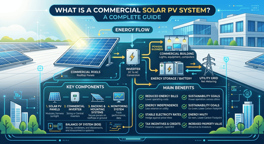
What Is a Commercial Solar PV System? A Complete Guide
A commercial solar PV system is a photovoltaic installation, typically ranging f...
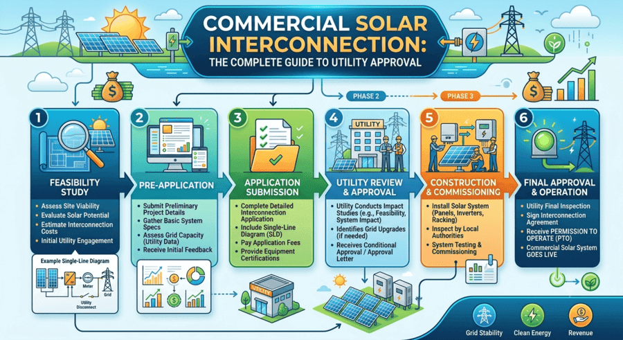
Commercial Solar Interconnection: Complete Guide To Grid Connection
Learn how solar farms connect to the grid. Explore interconnection processes, ti...

Benefits of Commercial Solar Panels: Why Businesses Are Switching to Solar Energy
Commercial solar panels help businesses lower electricity expenses, reduce expos...