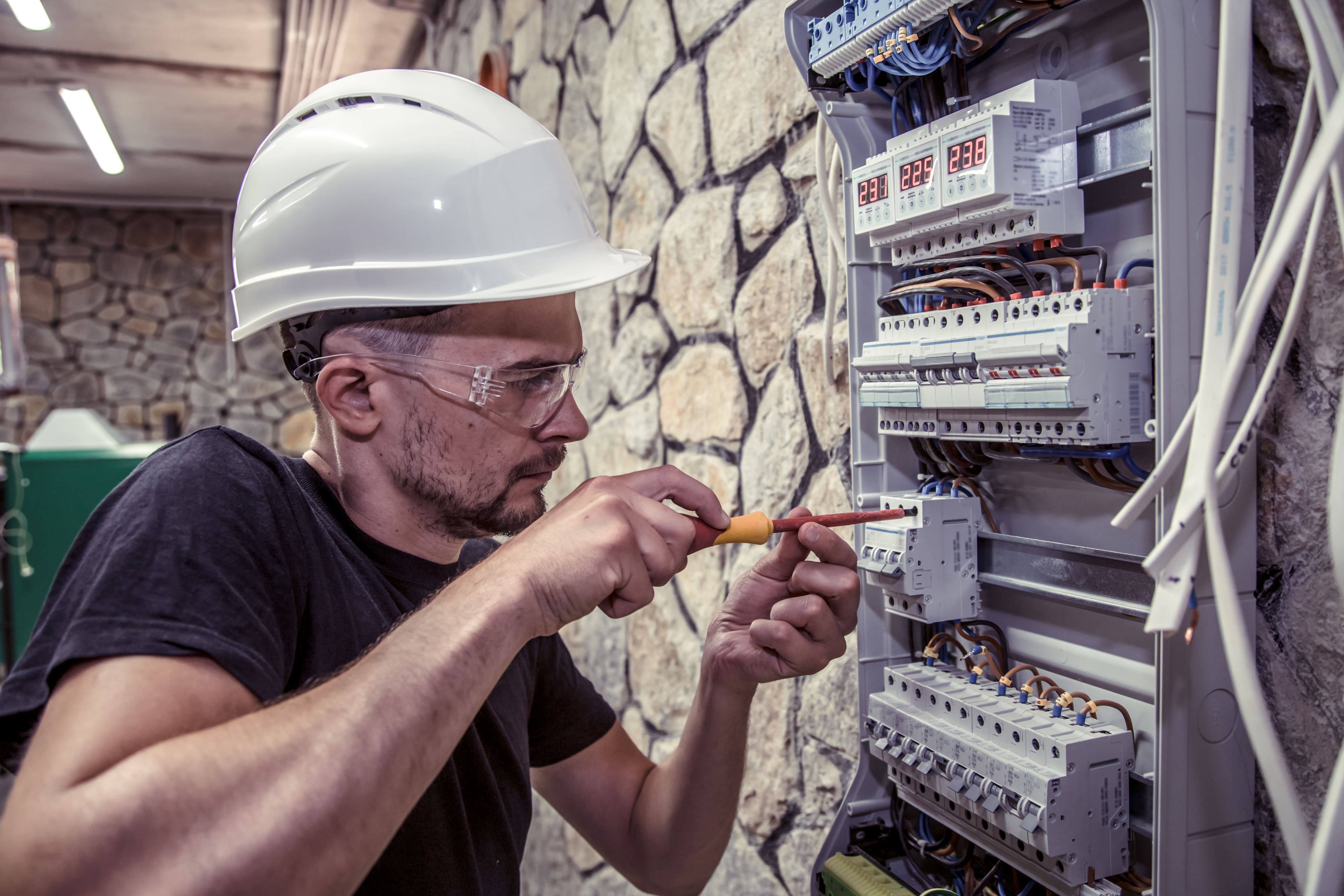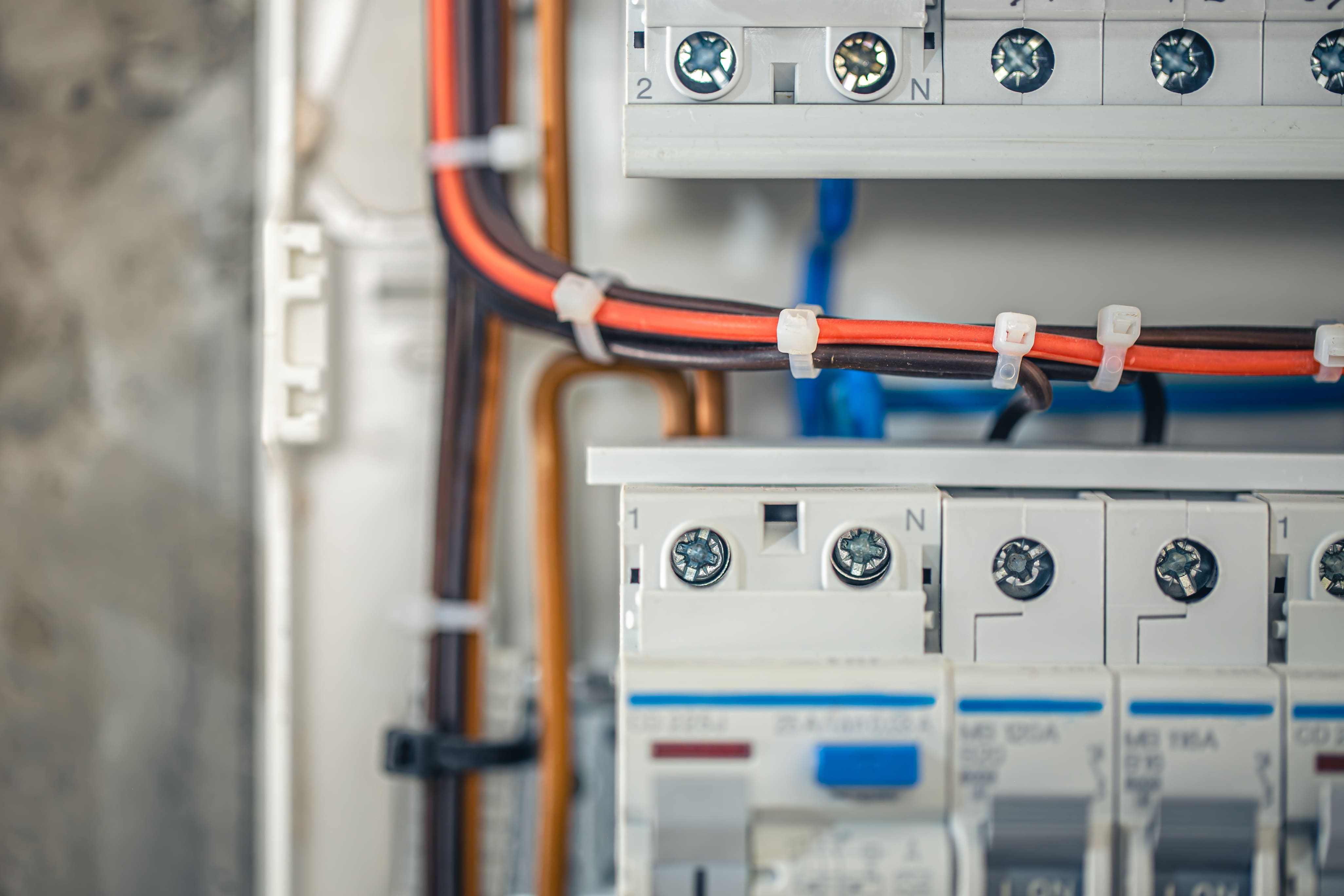

What types of electrical panels work with solar and battery systems? The main breaker panel is the most common choice for residential solar installations, using a load-side backfeed breaker to connect the inverter's AC output directly to the busbar. Main lug panels and meter-main combinations require special handling under NEC 705.12's 120% rule or supply-side tap connections. Subpanels serve as alternatives when the main panel lacks breaker space, while outdoor NEMA 3R enclosures accommodate exterior installations.
The connection method depends on your panel type: standard main breaker panels accept backfeed breakers in most jurisdictions, older fuse panels typically require replacement before solar integration, and subpanels need proper neutral-ground separation to meet code.
For whole-home battery backup integration: position your battery inverter close to the electrical panel to minimize voltage drop, follow NEC Articles 690 and 705 for proper overcurrent protection and disconnects, and confirm your utility's specific interconnection requirements before finalizing the design, since some utilities prohibit load-side connections entirely while others restrict system size based on transformer capacity.
This comprehensive guide examines practical panel options, explains connection methods for solar inverters, and demonstrates how proper panel selection streamlines permit approval while maximizing system performance.

Matching your panel type to your solar and storage objectives requires understanding how each configuration handles incoming power and distributes loads throughout your home.
Most residential solar-battery installations utilize a main breaker panel as the interconnection point, add subpanels where circuit density demands additional capacity, and employ transfer switches to manage source selection during grid outages.
A main breaker panel includes the service disconnect within the panel enclosure, making it the standard residential configuration. Main lug panels lack internal overcurrent protection and typically function as subpanels fed from upstream protection devices.
The most common solar installation method uses a load-side backfeed breaker in the main panel. This dedicated breaker connects the inverter's AC output directly to the panel's busbar, allowing solar power to feed household loads and export excess generation to the grid. Utilities widely accept this approach, and installers prefer it for straightforward code compliance.
Load-Side Connection Requirements:
Main lug panels and meter-main combinations require careful analysis of NEC interconnection methods. Installers must either:
These panels often appear in outdoor service equipment or manufactured housing, where the service disconnect exists separately from the distribution panel.
When integrating battery storage, position the battery inverter connection point where it can support both solar charging and load backup, minimizing wire runs between components and reducing voltage drop across the system.
Understanding how solar inverters physically connect to your electrical system helps you work effectively with installers and inspectors.
This standard approach installs a breaker in your existing panel specifically for the solar inverter. The inverter "backfeeds" power onto the busbar, making solar energy available to circuits throughout your home. Any excess production flows back through your utility meter.
Critical compliance points:
Supply-side taps connect solar generation upstream of the main panel overcurrent protection. This method bypasses the 120% rule limitations but requires:
Installers select supply-side connections when panel busbar ratings cannot accommodate additional backfed breakers or when utility rules mandate this approach. Learn more about supply-side vs load-side interconnection to determine the best option for your project.
When your main panel lacks available breaker spaces, adding a subpanel provides room for the solar breaker. Feed the subpanel from the main panel, then install the inverter breaker in the subpanel, typically positioned at the supply end of the subpanel busbar to satisfy code requirements.
Subpanel solar integration benefits:
Critical subpanel wiring rule: Keep neutral and ground bars separated in subpanels, bonding them only at the main service disconnect. This prevents improper current flow and protects against shock hazards, as detailed in our solar grounding and bonding guide.
Meter-main combinations integrate metering and main disconnect in a single enclosure, typically mounted outside. Solar interconnection follows similar principles but must account for the unique busbar configuration. The 120% rule frequently applies, and installers must verify that combined utility and solar breaker ratings stay within acceptable limits.
Feed-through panels distribute power from an upstream source to multiple downstream panels. Solar connections require careful load analysis to prevent overloading any section of the distribution system.
The inverter architecture affects how solar generation integrates with your electrical system.
Microinverters convert DC power to AC at each solar module. The AC output from multiple microinverters combines into branch circuits that terminate at a single breaker in your panel. This distributed conversion approach eliminates DC wiring in your home but requires attention to branch circuit ratings and proper GFCI protection. Proper DC connector installation remains critical even with microinverter systems to prevent fire hazards at the module level.
String inverters centralize conversion, connecting multiple solar modules in series and converting their combined DC output to AC. A single AC circuit from the inverter connects to your panel through a dedicated breaker. String systems simplify panel integration but concentrate equipment at one location. Compare different solar inverter types to understand which works best for your installation.
Battery systems add complexity through AC coupling or DC coupling approaches:

National Electrical Code articles 690 and 705 govern photovoltaic system installation and interconnection. Understanding key NEC requirements prevents inspection failures and ensures safe operation.
This rule limits the combined rating of the main breaker and any backfed inverter breakers to 120% of the panel's busbar rating. For a panel with a 200A busbar:
Alternatively, position the solar breaker at the opposite end of the busbar from the main breaker, allowing the busbar to handle current from both directions without exceeding ratings at any point.
Article 690 addresses:
Every jurisdiction enforces these requirements, though local amendments may add stricter standards.
NEC often requires inverter breakers at the supply end of the busbar (opposite the main breaker) to distribute current loading evenly. Permanent labels must identify:
Labels remain legible throughout the system's lifetime and survive normal environmental exposure.
Local utilities establish interconnection requirements that supplement NEC rules. Common utility requirements include:
Application and Documentation:
Technical Requirements:
Metering Provisions:
Some utilities prohibit load-side connections entirely, requiring supply-side taps for all solar installations. Others restrict system size based on service transformer capacity. Always confirm local utility rules early in your project planning to avoid costly redesigns.
Specific situations benefit from additional panel installations beyond your main service panel.
Install subpanels near large loads or load clusters to:
When solar panel space is limited, a subpanel dedicated to solar interconnection keeps the main panel available for household circuits.
NEMA 3R enclosures provide weather protection for panels mounted on exterior walls or on service pedestals. These rated enclosures resist rain, ice, and snow while maintaining safe operation. Use outdoor-rated equipment when:
Multi-inverter installations or complex battery systems may use dedicated solar distribution panels or AC combiner boxes. These panels:
Fuse panels and obsolete circuit breaker panels present challenges for solar integration. Most jurisdictions prohibit solar connections to:
Upgrade Path for Obsolete Equipment:
While panel replacement adds project cost, it eliminates safety hazards and provides a code-compliant platform for solar integration that supports future expansion.

Complete documentation and code-compliant installation practices reduce approval time and prevent inspection failures.
Essential Documentation Package:
Plan review and inspection coordination with your AHJ (Authority Having Jurisdiction) early in the project. Address questions during plan review rather than during field inspection to avoid project delays.
Successful solar-battery installations begin with clear understanding of how your electrical panel connects all system components. Work with licensed electricians who understand both solar interconnection methods and battery integration requirements.
Project Planning Sequence:
Your electrical panel serves as the central integration point where utility power, solar generation, and battery storage come together. Proper panel selection, compliant connection methods, and complete documentation ensure your system performs reliably from commissioning through decades of operation. Whether you need residential solar design, commercial solar design, or off-grid solar system design, understanding electrical panel integration is essential. Review our guide on understanding three-line diagrams for comprehensive system documentation.
Selecting the appropriate electrical panel configuration and solar connection method forms the foundation of a reliable, code-compliant solar-battery system. Whether you're installing a load-side backfeed breaker in a main panel, adding a subpanel to accommodate limited breaker space, or executing a supply-side tap for high-capacity systems, each approach must align with NEC requirements, utility interconnection rules, and your specific backup priorities. Work closely with licensed electricians who understand both solar integration and battery storage to ensure your panel selection supports seamless operation, passes inspection on the first attempt, and provides the flexibility to expand your system as your energy needs evolve. Proper planning at the panel level translates directly to long-term system performance and peace of mind during grid outages. Explore the Department of Energy's homeowner's guide for additional resources on residential solar systems.
Can a 100A service handle both solar panels and a whole-home battery system?
A 100A service can support solar and battery when your load audit confirms all continuous loads stay within service capacity limits. Size your inverter appropriately for the service rating, and manage high-draw appliances carefully. Inspectors may mandate a 200A upgrade if nameplate ratings exceed service capacity or if you plan future EV charging installation. Perform detailed electrical load calculations before finalizing equipment selections.
What wiring differences exist between main panels and subpanels for neutral and ground?
Main service panels bond neutral and ground bars together, creating the system grounding point. Subpanels keep these bars completely separated, running separate neutral and ground conductors back to the main panel. Never bond neutral and ground at a subpanel, this creates dangerous parallel ground paths and causes improper current flow. Use four-wire feeds (two hots, neutral, ground) for all subpanel connections, and verify separation with continuity testing.
Are used circuit breakers acceptable for solar installations?
Only use breakers specifically listed and approved for your panel manufacturer and model. Most manufacturers prohibit interchanging breakers between brands due to different bus stab designs, trip characteristics, and mounting dimensions. Using incompatible breakers creates overheating risks, violates panel listings, and causes automatic inspection failure. Purchase new breakers matching your panel manufacturer's specifications from trusted suppliers like Siemens, Eaton, or Schneider Electric to maintain safety certifications and warranty coverage.
Where should battery and inverter equipment be located relative to the electrical panel?
Position battery and inverter as close to the electrical panel as practical, minimizing conductor length and reducing voltage drop. Follow manufacturer clearance requirements for ventilation, avoid direct sunlight exposure, and keep equipment away from moisture sources. Provide adequate air circulation around components. Run conduit with gentle bends rather than sharp angles. Keep flammable materials and corrosive chemicals away from equipment rooms. In seismic zones, use proper anchoring methods to prevent equipment displacement during earthquakes.
How do I prepare documentation that speeds utility and permit approval?
Compile a complete technical package including single-line diagram, detailed load calculations, equipment specification sheets with UL certifications, and clear labeling plan. Document service capacity, grounding configuration, and interconnection method explicitly. Include commissioning procedures and testing protocols. Coordinate with utility interconnection staff early to understand metering and communication requirements specific to your service territory. Submit organized, complete applications that answer reviewer questions preemptively, reducing revision cycles and accelerating final approval.
We are dedicated to providing top-notch solar permit services to homeowners, business owners, DIY, and solar installers. Contact us today.