What is the SolarEdge SE40KUS inverter?
The SolarEdge SE40KUS is a 40-kilowatt three-phase commercial solar inverter rated for 277/480-volt electrical service commonly found in commercial buildings, warehouses, and industrial facilities across North America.
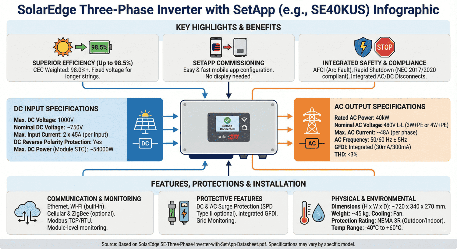
Core specifications include:
- Power output: 40 kW AC continuous (70 kW max DC input)
- Voltage range: 840-1000 Vdc operating, 1000 Vdc maximum
- Output current: 48.25 amperes per phase
- Efficiency:** 98.5% CEC weighted efficiency
- Certifications: UL 1741 SA/SB, IEEE 1547-2018, Rule 21 compliant
- Operating conditions:** -40°F to +140°F (-40°C to +60°C), NEMA 3R outdoor rated
- Safety features: Integrated arc fault protection, rapid shutdown, DC safety switch
- Manufacturing: USA-made, domestic content tax credit eligible
Why three-phase inverters are different
Installing a commercial solar system with a three-phase inverter requires different permitting documentation than residential systems. Commercial three-phase installations operate at 277/480V compared to residential 240V single-phase systems, requiring specialized breaker sizing, wire calculations, and neutral-ground bonding configurations that comply with NEC Articles 690 and 705.
What this guide covers
This comprehensive installation and permitting guide walks you through everything you need to know about the SE40KUS inverter, including:
- Technical specifications – Complete electrical ratings for permit documentation
- String sizing calculations- How to stay below 1000 Vdc maximum voltage
- One-line diagram creation- Proper three-phase AC/DC connection details
- NEC compliance – 125% breaker sizing rule, wire ampacity, busbar calculations
- Common permit rejections – String voltage errors, neutral-ground bonding mistakes
- Inspection preparation – Electrical tests, safety system demonstrations, documentation checklist
Whether you’re a commercial property owner, solar installer, or facility manager planning a solar installation, understanding the specific requirements for three-phase systems is essential for smooth permit approval and successful project completion.

Understanding Three-Phase Solar Systems
What is a three-phase system?
Three-phase electrical power is the standard for commercial and industrial buildings in North America. Unlike residential homes that typically use single-phase 240V service, commercial buildings use three-phase 277/480V power, delivering more efficient power for large loads and higher capacity with smaller conductors.
The 277/480V designation refers to 277 volts line-to-neutral and 480 volts line-to-line. Common applications include office buildings, retail centers, warehouses, manufacturing facilities, schools, hospitals, and multi-family properties with centralized electrical service. Understanding solar permit timeline expectations helps you plan your commercial project effectively.
SolarEdge SE40KUS Key Specifications
The SE40KUS is specifically designed for commercial solar installations on North American three-phase electrical services with proper UL and IEEE certifications for the U.S. market.
Rated AC Power Output: 40,000 W (40 kW) continuous AC power to the grid.
Voltage Requirements: 244-277-305V line-to-neutral, 422.5-480-529V line-to-line with 3W+PE or 4W+PE configurations.
Maximum DC Input: 70,000 W DC input power, representing a 1.75:1 DC-to-AC ratio for optimal energy production.
Operating Voltage Range: 840-1000 Vdc. Your string configuration must keep voltage within this range under all temperature conditions. Maximum input voltage is 1000 Vdc.
Efficiency Ratings: 98.5% CEC weighted efficiency means more solar energy reaches the grid rather than being lost as heat.
U.S. Certifications: UL 1741 SA and SB certification, IEEE 1547-2018 standard, Rule 21 (California), Rule 14 (Hawaii), UL 1699B arc fault protection, and CSA C22.2#107.1 Canadian standards.
Critical Specifications for Solar Permit Plan Sets
Electrical Specifications Required by AHJs
Authority Having Jurisdiction (AHJ) reviewers examine specific technical specifications when reviewing commercial solar permits. Complete and accurate inverter data is essential for approval, particularly when navigating solar permit services requirements.
DC Input (Solar Array Side) Specifications:
Maximum DC power of 70,000 W determines your maximum array size. Operating voltage range 840-1000 Vdc defines string configuration parameters. Maximum input voltage is 1000 Vdc, which must never be exceeded even under worst-case cold temperature conditions.
Maximum input current is 48.25 Adc. The SE40KUS accepts three DC input pairs (fuse less), allowing flexible array configurations. Wire sizing for DC inputs must accommodate this current with appropriate NEC safety factors. Your solar engineering requirements for permits documentation should include calculations showing AWG 6-12 copper wire properly sized for DC currents.
The inverter includes reverse polarity protection, which should be noted in safety features documentation.
AC Output (Grid Side) Specifications:
The SE40KUS delivers 40,000W rated AC power with maximum continuous output current of 48.25A per phase. AC voltage specifications show 480V line-to-line and 277V line-to-neutral (nominal), with operating range 244-305 Vac line-to-neutral and 422.5-529 Vac line-to-line.
The inverter supports both 3-wire + PE and 4-wire + PE connection configurations. Most commercial three-phase installations use 4-wire + PE (three phase conductors, one neutral conductor, and protective earth ground). Your one-line diagram must clearly show which configuration you’re using and must coordinate with utility interconnection requirements.
Total Harmonic Distortion (THD) is ≤3%, meeting utility power quality requirements. Power factor range is adjustable from +/-0.85 to 1, allowing grid support services or meeting utility-specific power factor requirements as outlined in DOE IEEE 1547 guidance.
Safety Certifications to Document:
Include all relevant U.S. certifications in your permit package. The SE40KUS complies with UL 1741 SA and SB, the gold standard for grid-connected inverters in North America. The “SA” and “SB” designations indicate advanced grid support functions meeting California Rule 21 requirements.
NREL IEEE 1547 resources govern how distributed energy resources connect to utility grids. UL 1699B arc fault protection compliance meets NEC Article 690 requirements. The inverter also meets CSA C22.2#107.1 Canadian standards and FCC Part 15 Class A emissions requirements.
Physical Installation Specifications
Your plan sets must show inverter mounting details and environmental specifications. The SE40KUS with integrated safety switch measures 808mm H × 317mm W × 300mm D (31.8″ × 12.5″ × 11.8″) and weighs 35.5kg (78.2 lbs).
Include mounting clearances: adequate space above and below for fan ventilation, and sufficient clearance in front for operation and maintenance per NEC Article 110.26. The NEMA 3R outdoor rating allows outdoor installation with protection against rain, sleet, and ice formation.
Operating temperature range is -40°C to +60°C (-40°F to +140°F), covering virtually all North American climate zones. The inverter uses fan cooling with user-replaceable fans for long-term serviceability. Noise level is less than 62 dBA, quieter than normal conversation.
Safety Features to Document
Integrated Type II DC and AC surge protection (field-replaceable) protects from lightning and surge events. Show surge protection devices on your one-line diagram.
Ground-fault isolation detection monitors at 167 kΩ sensitivity, continuously checking for ground faults. When detected, the inverter shuts down and displays a fault code. This specification should be noted in your grounding and bonding documentation.
Integrated arc fault protection complies with UL 1699B and is user-configurable per NEC Article 690.11. Include a note: “Arc fault protection integral to inverter, compliant with NEC 2014-2023 Article 690.11 and UL 1699B.”
The Photovoltaic Rapid Shutdown System meets NEC 2014-2023 Article 690.12 when paired with C651U power optimizers, providing automatic rapid shutdown upon AC grid disconnect.
The integrated DC safety switch eliminates the need for external DC disconnects in many jurisdictions, simplifying installation.
Creating Your Electrical One-Line Diagram
DC Side String Configuration
Proper string sizing requires careful voltage calculations. Start with your module specifications: open-circuit voltage (Voc), short-circuit current (Isc), maximum power voltage (Vmp), and temperature coefficients.
Calculate string voltage at Standard Test Conditions (STC) by multiplying modules in series by module Voc. Next, calculate the worst-case cold temperature voltage. Module voltage increases as temperature decreases, typically 0.3-0.4% per degree Celsius.
For example, with modules rated at 40V Voc and the coldest ambient temperature of -20°C, module temperature might reach -40°C. With a temperature coefficient of -0.35%/°C: 40V × [1 + 0.0035 × (25-(-40))] = 40V × 1.23 = 49.2V. A string of 20 modules would produce 984 V, safely under the 1000 Vdc maximum.
Your plan sets must show these calculations clearly, demonstrating that string voltage never exceeds 1000 Vdc. String current calculations are equally important. With three string inputs and 48.25 A maximum input current, calculate the maximum current from each string and verify the total parallel current stays within limits.
The SE40KUS works with SolarEdge power optimizers. Each module connects to a power optimizer performing module-level maximum power point tracking. Your plan sets should specify “Each module equipped with SolarEdge C651U power optimizer per manufacturer requirements.”
AC Side Connection Details
Your one-line diagram must clearly show the three-phase AC connection configuration. Most installations use 4-wire + PE: three-phase conductors (L1, L2, L3), one neutral conductor (N), and protective earth ground (PE).
Breaker Sizing:
NEC requires overcurrent protection devices for continuous loads to be sized at 125% of maximum continuous current. The SE40KUS outputs 48.25 A maximum continuous per phase: 48.25A × 1.25 = 60.3A minimum. The next standard breaker size is 70A. Show: “70A 3-pole breaker per NEC 705.12, sized at 125% of 48.25A maximum continuous output current.”
Wire Sizing:
AC wire sizing accounts for continuous current with safety factors and derating. Start with 48.25A maximum continuous, and multiply by 1.25 to get 60.3A. Select wire with ampacity meeting or exceeding this after derating factors.
The datasheet specifies AWG 6-10 for AC connections. Most commercial installations use AWG 6 copper conductors for phase conductors, providing capacity accounting for derating factors like ambient temperature and conduit fill. Specify: “3 #6 AWG THWN-2 + 1 #6 AWG neutral + 1 #6 AWG ground in 1″ EMT conduit.”
Neutral and Ground Connections:
The SE40KUS is transformer-less (ungrounded) on the DC side. The AC side must be properly grounded through the building’s grounding electrode system. Show the neutral connecting to the neutral bus in the service panel and the equipment grounding conductor connecting to the grounding bus. Never bond neutral to ground except at the main service entrance per NEC Article 250.
Busbar Calculations:
NEC 705.12 requires that for load-side connections, the solar breaker rating plus the main breaker rating cannot exceed 120% of the panel busbar rating. With a 400A busbar panel and a 400A main breaker, the maximum solar breaker = (400A × 1.20) – 400A = 80A. The 70A solar breaker fits within this limit.
Protection Equipment on One-Line
Show all protection and safety equipment: AC disconnect (integrated safety switch or separate lockable disconnect), integrated DC disconnect, surge protection devices (AC and DC sides), ground fault protection (167 kΩ sensitivity), arc fault circuit interruption notation, and rapid shutdown initiation points following NEC rapid shutdown compliance.
Include a legend explaining symbols, abbreviations, and line types using standard electrical symbols.

Solar Permit Solutions
Commercial Solar Design Services
Professional permit plan sets for commercial installations. PE-stamped, code-compliant, fast delivery.
Safety and Code Compliance
Rapid Shutdown Compliance
NEC 2014-2023 requires rapid shutdown capabilities for commercial solar systems. The SE40KUS provides rapid shutdown when paired with C651U power optimizers, automatically activating upon AC grid disconnect.
Document clearly: “Photovoltaic rapid shutdown compliant with NEC 2014-2023 Article 690.12. SolarEdge power optimizer system automatically reduces DC voltage upon loss of AC power or manual shutdown via integrated safety switch.”
Show the rapid shutdown initiation device (integrated safety switch) clearly on your one-line diagram with proper labeling: “RAPID SHUTDOWN SWITCH” or similar permanent marking.
Ground Fault and Arc Fault Protection
The SE40KUS monitors ground fault isolation at 167 kΩ sensitivity. Equipment grounding conductor sizing follows NEC Article 250. For the 70A breaker, NEC Table 250.122 requires a minimum #8 copper or #6 aluminum equipment grounding conductor.
Arc fault protection complies with UL 1699B. During inspection, be prepared to demonstrate the arc fault protection self-test function.
Islanding Protection
Anti-islanding protection prevents the inverter from energizing utility lines during grid outage. The inverter monitors voltage, frequency, and impedance, disconnecting within milliseconds when detecting utility disconnection. Note: “Anti-islanding protection compliant with IREC IEEE 1547 adoption tracker and UL 1741.”
Communication and Monitoring
The SE40KUS supports 2x RS485 interfaces, Ethernet connectivity, and optional cellular communication. Document your communication method: “Inverter monitoring via Ethernet connection to building network.”
The SetApp mobile application simplifies commissioning via a built-in Wi-Fi access point for local connection. Include: “Inverter commissioning performed via SolarEdge SetApp mobile application with module-level monitoring verification.”
Smart Energy Management includes export limitation features controlling power export to the grid. Your utility interconnection agreement may specify export limitations. Understanding different inverter types helps optimize your system design.
Installation Location Requirements
The SE40KUS operates from -40°C to +60°C (-40°F to +140°F). The NEMA 3R outdoor rating provides protection against rain, sleet, and ice. The inverter uses fan cooling, requiring adequate clearance: 12 inches above and below, and 6 inches on each side.
NEC Article 110.26 mandates working clearances. Provide at least 3 feet of clear working space in front. Mount the inverter 4-5 feet above the finished floor, putting controls and connections at a comfortable working height.
Wire entry uses conduit: ¾” or 1″ for AC output (AWG 6-10), ¾” or 1″ for DC input (AWG 6-12). Show actual wire size on plans with proper conduit specifications. Professional solar permit design tools can streamline this documentation process.
Common Permit Rejection Issues and Solutions
String Voltage Errors
Problem: String voltage exceeds 1000 Vdc at cold temperatures.
This is one of the most common rejection issues for commercial solar permits. Many designers calculate string voltage at standard test conditions but forget to account for voltage increases at cold temperatures.
Solution: Always calculate worst-case cold temperature voltage and document it clearly in your plan sets. Use the coldest expected ambient temperature for your location. Account for module temperature being approximately 20°C colder than ambient under cold, high-irradiance conditions. Apply the module’s temperature coefficient to calculate cold temperature Voc.
Show your calculations step-by-step in the plan sets: “Coldest expected ambient: -20°C. Module temperature: -40°C. Module Voc at STC: 40.5V. Temperature coefficient: -0.33%/°C. Cold temperature Voc: 40.5V × [1 + 0.0033 × (25-(-40))] = 40.5V × 1.21 = 49.0V. String of 20 modules: 20 × 49.0V = 980V. Maximum voltage 980V < 1000V limit ✓"
If your calculation shows voltage exceeding 1000V, reduce the number of modules per string and recalculate.
Three-Phase Connection Errors
Problem: Incorrect neutral-ground bonding documented.
Three-phase systems often confuse installers familiar with residential single-phase installations. Common errors include bonding neutral to ground at the inverter (which should only happen at the service entrance), incorrectly sizing the neutral conductor, or failing to show proper 4-wire + PE configuration.
Solution: Clearly show the 4-wire + PE configuration on your one-line diagram with proper labeling: three phase conductors (L1, L2, L3), one neutral conductor (N), and one equipment ground (PE or G). Show the neutral connecting to the neutral bus in the service panel, and the ground connecting to the grounding bus. Include a note: “Neutral bonded to ground at service entrance only per NEC 250.24. No neutral-ground bond at inverter.”
For the SE40KUS transformer-less design, add a note explaining the DC system grounding: “DC system isolated from ground (transformer-less design). Ground fault isolation monitored at 167kΩ sensitivity. Equipment grounding conductor provides fault current path only.”
Breaker and Wire Sizing Issues
Problem: Breaker not sized at 125% continuous current.
NEC requires overcurrent protection for continuous loads to be sized at 125% of the maximum continuous current. Many plan sets show breakers sized exactly at the inverter’s output current rating, which violates this requirement.
Solution: Always show the 125% calculation clearly: “SE40KUS maximum continuous output current: 48.25A per phase. Required breaker rating: 48.25A × 1.25 = 60.3A minimum. Installed breaker: 70A (next standard size up) per NEC 705.12.”
Wire sizing must follow the same principle. Show wire ampacity calculations including all derating factors: “Required wire ampacity: 48.25A × 1.25 = 60.3A. Installed: #6 AWG THWN-2 copper (75A rating at 75°C) with temperature derating factor 0.91 for 45°C ambient = 68.25A adjusted ampacity. Meets 60.3A requirement ✓”
Busbar Capacity Violations
Problem: Exceeding 120% busbar rating in service panel.
NEC 705.12(D)(2) requires that for load-side connections, the sum of the solar breaker rating plus the main breaker rating cannot exceed 120% of the panel’s busbar rating. Many designs violate this rule, particularly when adding solar to panels that are already fully loaded.
Solution: Calculate and document the 120% rule clearly: “Panel busbar rating: 400A. Main breaker: 400A. Solar breaker: 70A. Check: (400A + 70A) ≤ (400A × 1.20) = 480A. 470A ≤ 480A ✓ Complies with NEC 705.12(D)(2).”
If your calculation shows a violation, you have three options: use a supply-side connection (before the main breaker), install a dedicated solar service panel, or derate the main breaker. Document which approach you’re using and show all calculations.
Missing Certifications
Problem: AHJ requires specific certifications not included in permit package.
Commercial solar permits often require more extensive certification documentation than residential permits. Missing certifications cause delays and resubmissions.
Solution: Include a complete certifications package with your permit application: IEC-62109 and AS3100 safety compliance, BDEW or CEI-016 grid connection compliance (or IEEE 1547 for U.S. installations), UL1699B arc fault protection certification, IEC61000 series emissions compliance, and RoHS environmental compliance.
Attach the complete SolarEdge datasheet, which includes most of these certifications. For certifications not shown on the datasheet, download them from SolarEdge’s website or contact technical support to obtain them. States like California and Texas have specific certification requirements.
Inadequate Monitoring Documentation
Problem: Jurisdiction requires monitoring documentation for commercial systems.
Many commercial solar programs, incentives, or utility interconnection agreements require performance monitoring. Some jurisdictions mandate monitoring for all commercial systems over certain sizes.
Solution: Document your monitoring system completely in plan sets: communication method (Ethernet, RS485, Wi-Fi, or cellular); connection details showing communication wiring on plans; monitoring capabilities, noting “Module-level monitoring via SolarEdge power optimizers provides real-time performance data, fault detection, and historical energy production tracking”; data access, stating “Monitoring portal accessible via web browser and mobile app”; and alert capabilities, explaining “System sends automatic alerts for faults, underperformance, or communication issues.”
Include screenshots from the SolarEdge monitoring portal showing the layout view with module-level data, system performance graphs, and alert configuration options.
Inspection Preparation
Pre-Inspection Checklist
Before scheduling your final inspection, complete a thorough verification checklist to ensure everything is ready.
Electrical Tests:
- Measure and record string voltages at DC input
- Verify phase-to-phase voltage: should read approximately 480V
- Verify phase-to-neutral voltage: should read approximately 277V
- Test ground continuity from inverter to service panel ground bus
- Measure insulation resistance from DC+ to ground and DC- to ground (should read >100MΩ)
- Verify correct phase rotation (clockwise: L1-L2-L3)
Safety System Tests:
- Run arc fault protection self-test per manufacturer instructions
- Test ground fault detection system
- Demonstrate rapid shutdown function if installed (measure voltages before and after shutdown)
- Verify anti-islanding protection (may require utility representative)
Documentation Preparation:
Organize a comprehensive inspection package: approved permit plans (stamped and signed), as-built drawings if installation differs from approved plans, a complete inverter datasheet with certifications, a SetApp commissioning report showing all modules detected, string voltage calculation sheets, wire and breaker sizing calculations, test results and voltage measurements, and installation photographs showing inverter mounting, wire connections, labeling, and overall system.
Common Inspector Questions
Be prepared to answer these frequent inspector questions:
“How does the arc fault protection work?” Explain that the inverter continuously monitors DC circuits for characteristic arc fault signatures. If arcing is detected, the inverter shuts down within seconds. Offer to demonstrate the self-test function.
“Demonstrate the rapid shutdown function.” If installed, show the AC disconnect marked as the rapid shutdown initiation device. Measure DC voltage at multiple points, activate the disconnect, and show voltage dropping to safe levels within seconds.
“Show me the string voltage calculations.” Point to your calculation sheet showing Standard Test Conditions voltage and worst-case cold temperature voltage, demonstrating that maximum voltage stays below 1000 Vdc.
“Where are the AC and DC disconnects?” Point out the AC disconnect (may be integrated into the inverter or a separate device) and DC disconnect/safety unit. Verify they’re properly labeled and accessible.
“How is the neutral bonded in this three-phase system?” Explain that the neutral bonds to ground only at the service entrance per NEC 250.24. Show that the inverter’s neutral connects to the neutral bus in the service panel, and the equipment ground connects to the grounding bus, with no neutral-ground bond at the inverter.
“What’s the monitoring and alert system?” Demonstrate the SetApp application or monitoring portal, showing real-time system data, module-level monitoring, and alert configuration.
Final Inspection Tips
Make the inspector’s job easier: label all disconnects clearly with permanent professional labels, ensure all covers and access panels are properly installed, have a calibrated multimeter ready for any requested measurements, be prepared to demonstrate SetApp monitoring and commissioning report, keep the complete inverter installation manual on-site for reference, and stay professional and cooperative.

Maintenance and Warranty
Maintenance Requirements
The SE40KUS is designed for minimal maintenance, but some routine checks ensure continued performance and reliability following NREL commercial solar best practices.
Fan Inspection and Replacement: The cooling fan is user-replaceable and typically requires inspection annually. Check for unusual noise, reduced airflow, or visible damage. Replacement fans are available from SolarEdge and can be swapped by qualified technicians without removing the inverter from the wall.
Visual Inspections: Perform monthly or quarterly visual inspections checking for any signs of overheating (discoloration, melting, burning smells), verifying that ventilation openings remain clear of dust, debris, or obstructions, checking that all displays and LED indicators show normal operation, and inspecting conduits and external wiring for any damage or deterioration.
Performance Monitoring Review: Review monitoring data regularly for unusual performance patterns, sudden drops in energy production, increasing numbers of fault events, or individual modules showing significantly different output than neighbors. The module-level monitoring capability makes it easy to spot developing issues before they become serious problems.
Connection Torque Verification: Annually, verify that all wire terminations remain tight. Thermal cycling can cause connections to loosen over time. Follow manufacturer specifications for proper torque values.
Surge Protection Device Checks: The integrated Type II DC surge protection is field-replaceable. After lightning events or major surge activity, inspect SPDs for damage and replace if necessary. Optional AC surge protection devices should be similarly monitored.
Warranty Documentation
Most SolarEdge commercial inverters include a standard 12-year warranty covering defects in materials and workmanship. Extended warranty options up to 20 years are available for purchase at the time of installation or within a specified period afterward.
What’s Covered: Typical warranty coverage includes manufacturing defects, component failures under normal use, firmware-related issues, and replacement of defective units. SolarEdge typically provides a replacement unit rather than repairing the original.
What’s Not Covered: Common warranty exclusions include damage from improper installation, use outside specified parameters (overvoltage, overcurrent, extreme temperatures beyond ratings), lightning or other external events (though surge protection may prevent this), unauthorized modifications or repairs, and normal wear and tear.
Registration Requirements: Most manufacturers require system registration within a specified period (often 30 days) to activate warranty coverage. For the SE40KUS, registration typically happens automatically when the system connects to the monitoring portal and begins reporting data. Verify registration by logging into your SolarEdge monitoring account and checking that the inverter appears with full warranty status.
Warranty Claims: Proper documentation for warranty claims should include proof of purchase (invoice or receipt), installation date documentation, the inverter serial number (found on the label), a description of the problem including any fault codes, a record of troubleshooting steps taken, and photographs showing the issue if applicable.
Contact SolarEdge technical support to initiate warranty claims. Most claims start with a diagnostic call to verify the issue is warranty-covered rather than an installation or configuration problem.
Troubleshooting Common Issues
Communication Failures: If monitoring shows “disconnected” or no data: check Ethernet cable connections and verify network switch port is active; for Wi-Fi, verify wireless network credentials and signal strength. For RS485, check wire connections and verify proper termination; for cellular, verify antenna connection and cellular signal availability, and restart the inverter communication interface via SetApp.
Ground Fault Errors: If the inverter displays ground fault errors, check for moisture in DC junction boxes or connections, inspect DC wiring insulation for damage, verify no DC conductors inadvertently contact ground, measure insulation resistance with a megohmmeter (should exceed 100kΩ), and check for damaged power optimizers or modules.
Arc Fault Triggers: If arc fault protection activates, inspect all DC connections for tightness, look for damaged wire insulation or crushed conductors, check MC4 connectors for proper mating and locking, verify no loose or corroded connections, and check for damaged power optimizers.
Grid Compliance Issues: If the inverter won’t connect to the grid or repeatedly disconnects, verify the utility voltage is within the 244-305V line-to-neutral range, check frequency stability (should be 60 Hz ±5%), verify impedance at the point of interconnection meets requirements, review utility interconnection settings in the inverter configuration, and contact the utility to verify no grid issues.
Conclusion
Successfully installing and permitting a commercial three-phase solar system requires careful attention to specifications, thorough documentation, and proper code compliance. The SolarEdge SE40KUS three-phase inverter simplifies many aspects of commercial solar installation with its integrated safety features, high efficiency, and flexible configuration options.
Key Takeaways
Critical Specifications:
- 40 kW rated AC output at 277/480 V three-phase
- 70 kW maximum DC input, 840-1000 Vdc operating range
- 48.25A maximum continuous output per phase
- 98.5% CEC weighted efficiency
- NEMA 3R outdoor rating, -40°C to +60°C
- UL 1741 SA/SB, IEEE 1547-2018, CPUC Rule 21 compliance
- Integrated arc fault protection and rapid shutdown
- USA-manufactured, domestic content eligible
Essential Documentation: Complete electrical specifications, detailed one-line diagram, string voltage calculations proving <1000 Vdc maximum, breaker/wire sizing with NEC 125% requirements, safety feature documentation, all certifications (UL, IEEE, Rule 21), and monitoring system specifications.
Common Pitfalls to Avoid: Inadequate cold temperature voltage calculations, incorrect neutral-ground bonding, breaker sizing without a 125% safety factor, busbar capacity violations, missing certifications, and insufficient monitoring documentation.
Professional Resources
Solar Permit Solutions provides professional permit design services for complex commercial installations. Professional plan sets include complete electrical diagrams, detailed calculations, wire and breaker sizing, structural calculations if required, and jurisdiction-specific compliance documentation.
NABCEP professional certification demonstrates professional competence in solar installation and enhances credibility with customers, inspectors, and AHJs. Understanding the difference between string inverters vs microinverters helps with proper system design decisions.
FAQs
What’s the difference between the SE40KUS and residential SolarEdge inverters?
The SE40KUS is designed for commercial three-phase electrical service (277/480V), while residential solar design inverters operate on single-phase service (240V). The SE40KUS delivers 40 kW compared to residential models maxing at 11.4 kW. Commercial three-phase systems require different permitting documentation, larger wire sizes, and three-pole breakers instead of two-pole breakers used residentially.
Commercial Solar Design Services
Professional permit plan sets for commercial installations. PE-stamped, code-compliant, fast delivery.
Frequently Asked Questions
The SE40KUS is designed for commercial three-phase electrical service (277/480V), while residential solar design inverters operate on single-phase service (240V). The SE40KUS delivers 40 kW compared to residential models maxing at 11.4 kW. Commercial three-phase systems require different permitting documentation, larger wire sizes, and three-pole breakers instead of two-pole breakers used residentially.
The SE40KUS accepts up to 70,000W DC input across three string inputs. With 400 W modules, you could install up to 175 modules (70,000 W ÷ 400 W = 175). Practical limits depend on string voltage constraints (must stay below 1000 Vdc at cold temperatures) and current constraints (48.25 A maximum per input). Most installations use 140-160 modules configured as three strings of 47-53 modules each.
AC wire sizing depends on 48.25 A maximum continuous output per phase. NEC requires wire with ampacity of at least 48.25A × 1.25 = 60.3A after derating. Most commercial installations use AWG 6 copper THWN-2 conductors for three-phase conductors, neutral, and ground, providing 75A ampacity at 75°C, accounting for typical derating factors.
Yes, the SE40KUS is USA-manufactured and, when paired with C651U power optimizers, is intended to be eligible for the enhanced federal income tax credit domestic content bonus under IRS Notices 2024-41 and 2025-08. Consult with your tax advisor regarding specific project eligibility.
PE stamp requirements vary by jurisdiction and system size. Many jurisdictions require professional engineer stamps for all commercial solar, while others only require PE stamps for systems above certain sizes (commonly 100 kW+) or specific roof types. Check with your local AHJ early in planning to determine PE requirements for your specific installation.
SPS Editorial Team
Solar Permit Solutions
Solar Permit Solutions provides professional solar permit design services for residential, commercial, and off-grid installations across all 50 states. Our team ensures permit-ready plan sets delivered fast.
Related Articles

Utility Interconnection Requirements for Solar Installers: The 6 Rules Every Utility Enforces
interconnection agreement, UL 1741 and IEEE 1547 certified inverters, a utility-...

How to Respond to Solar Permit Corrections (And Get Approved on Resubmission)
To respond to a solar permit correction, read every comment from every reviewing...

Can an EV Charging Station Be Powered by Solar? Here’s How to Build One
Yes, an EV charging station can be powered by solar. A grid-tied solar array pai...