Quick Answer: The Tigo TS4-A-F is a module-level rapid shutdown device that reduces solar panel voltage to 0.6V within seconds during emergencies, ensuring NEC 690.12 compliance for residential and commercial photovoltaic systems. These devices cost $30-50 per module installed and work with hundreds of UL PVRSS-certified inverters to protect first responders during fire suppression operations.
What is the Tigo TS4-A-F?
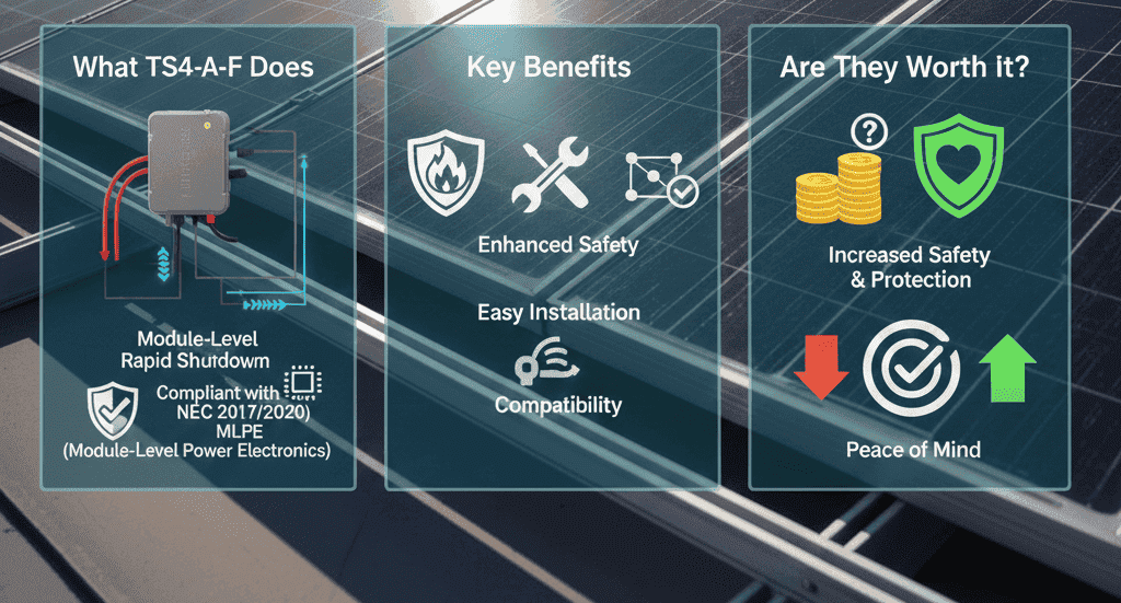
The TS4-A-F is a fire safety device that attaches directly to solar modules, providing rapid shutdown functionality required by the National Electrical Code Section 690.12. When activated, each unit reduces its output voltage from potentially lethal levels (up to 80V) to just 0.6V per module, creating safe working conditions for firefighters and emergency personnel within 30 seconds.
Key specifications at a glance:
- Voltage reduction: From 16-80V to 0.6V per unit
- Current capacity: 15A or 20A (Imp), 25A (Isc)
- Maximum wattage: 700W per unit (725W UL)
- System compatibility: 1500V UL / 1000V IEC
- Warranty: 25 years
- NEC compliance: 2014, 2017, 2020, 2023 code cycles
How TS4-A-F differs from alternatives: Unlike string-level disconnect switches that may leave dangerous voltages present across entire arrays, TS4-A-F provides module-level voltage control. This means a 20-module string reduces to only 12V total during shutdown (20 modules × 0.6V), far below the NEC’s 30V safety threshold inside array boundaries.
The device operates through Power Line Communication (PLC), using existing DC conductors to receive a continuous “keep-alive” signal from an RSS (Rapid Shutdown System) Transmitter. No additional control wiring is required, which simplifies installation and reduces material costs compared to systems requiring separate communication cables.
Common use cases:
- New residential solar installations requiring NEC compliance
- Commercial rooftop arrays on enclosed buildings
- Retrofit upgrades for existing systems without rapid shutdown
- String inverter systems lacking integrated shutdown functionality
- Jurisdictions enforcing strict module-level voltage control interpretations
The TS4-A-F addresses a critical safety mandate: protecting first responders from electrical shock hazards during emergency operations on buildings with solar installations. As solar adoption accelerates, with over 4.5 million residential installations across the United States as of 2024, understanding rapid shutdown requirements becomes essential for installers, permitting authorities, and system owners ensuring code compliance.

What is the Tigo TS4-A-F?
The TS4-A-F is a module-level rapid shutdown device designed to reduce electrical hazards during emergency situations. This fire safety add-on unit attaches directly to solar modules, enabling compliance with NEC 690.12 requirements that mandate voltage reduction to safe levels when rapid shutdown is activated.
Technical Specifications
The TS4-A-F operates within specific electrical parameters designed to accommodate modern high-efficiency solar modules:
Electrical Ratings:
- Maximum input voltage: 80V per module
- Operating voltage range: 16-80V
- Maximum input current (Imp): 15A or 20A models
- Maximum input current (Isc): 25A
- Maximum wattage: 700W per unit
- System voltage compatibility: 1500V UL / 1000V IEC
Physical Characteristics:
- Compact design for frame or rack mounting
- MC4 connectors (standard), with EVO2 options available
- Cable lengths: 0.12m, 1.2 m, and 1.3m options
- Weight: Approximately 340g per unit
- Operating temperature: -40°C to +85°C
The device reduces output voltage to 0.6V per module when the rapid shutdown signal is interrupted, resulting in total string voltages below 30V—well within the NEC’s safety threshold of 80V within the array boundary.
How TS4-A-F Units Function
The TS4-A-F operates through a sophisticated power line communication (PLC) system that monitors a continuous “keep-alive” signal transmitted over the existing DC conductors. This eliminates the need for additional control wiring, simplifying installation and reducing material costs.
The Rapid Shutdown Mechanism
During normal operation, the RSS Transmitter sends a continuous PLC signal through the DC conductors to each TS4-A-F unit in the array. The units remain in an “ON” state, passing full module voltage to the string. When rapid shutdown is initiated, either manually at the shutdown switch or automatically through loss of AC grid power, the transmitter ceases sending the keep-alive signal.
Within milliseconds, each TS4-A-F unit detects the signal loss and enters shutdown mode, reducing its output to 0.6V. For a typical 20-module string, this results in a total voltage of only 12V, making the array safe for emergency responders within the NEC-mandated 30-second window.
Component Requirements
A complete TS4-A-F rapid shutdown system requires three primary components:
- TS4-A-F Units: One device per module (or TS4-A-2F for two-module configurations)
- RSS Transmitter: Generates and monitors the PLC keep-alive signal
- Compatible Inverter: Many modern inverters include integrated RSS transmitter functionality
The RSS transmitter must be powered from the same AC branch circuit as the inverter, a critical requirement for NEC compliance that ensures simultaneous shutdown of both the DC array and AC disconnect.
Benefits of TS4-A-F Rapid Shutdown
Enhanced First Responder Safety
The primary benefit aligns with the original intent of NEC 690.12: protecting firefighters and emergency personnel from electrical shock hazards. Traditional solar installations maintain lethal DC voltages across conductors as long as sunlight reaches the modules. The TS4-A-F system reduces these voltages to negligible levels within seconds, enabling safe rooftop operations during fire suppression and rescue activities.
NEC Compliance Across Multiple Code Cycles
The TS4-A-F maintains UL PVRSS certification with hundreds of inverter models, ensuring compliance with:
- NEC 2014 Section 690.12
- NEC 2017 Section 690.12
- NEC 2020 Section 690.12
- NEC 2023 Section 690.12
This multi-cycle compatibility provides flexibility for installations in jurisdictions operating under different code adoptions, streamlining the permitting process regardless of local AHJ requirements.
Cost-Effective Module-Level Solution
Compared to alternative rapid shutdown technologies, the TS4-A-F offers several economic advantages:
Installation Efficiency:
- Snap-to-frame mounting eliminates additional hardware
- No separate grounding wire required
- PLC communication uses existing DC conductors
- Plug-and-play compatibility with certified inverters
System Scalability:
- A single transmitter serves entire array
- 1:1 module-to-device ratio maintains simplicity
- Compatible with strings up to 1,000 feet (with dual-core transmitter beyond this distance)
Retrofit Capability:
- Easily integrated into existing installations
- No requirement to replace modules or inverters
- Minimal labor hours for implementation
Reliability and Longevity
The TS4-A-F carries a 25-year warranty, matching typical solar module lifecycles. The devices contain no moving parts and operate in harsh outdoor environments without degradation, providing long-term reliability for system owners and reducing maintenance concerns over the installation’s lifespan.
Solar Permit Solutions
Need Solar Permit Plans?
Professional, permit-ready solar plan sets delivered fast. Residential and commercial projects across all 50 states.
TS4-A-F in Solar Permitting and Plan Sets
Code Compliance Documentation
Including TS4-A-F components in permit applications requires specific documentation to demonstrate NEC 690.12 compliance:
Required Plan Set Elements:
- Single-Line Diagram: Must clearly show TS4-A-F placement at each module, RSS transmitter location, and signal path through DC conductors to the inverter.
- Specification Sheets: Include manufacturer datasheets for TS4-A-F units, RSS transmitter, and compatible inverter showing UL PVRSS certification numbers.
- Electrical Calculations: Demonstrate that maximum string voltage during shutdown (0.6V × number of modules) remains below the 30V threshold required by NEC 690.12(B).
- Equipment Placement: Show mounting locations for the RSS transmitter, verifying it’s on the same AC branch circuit as the inverter.
- Labeling Details: Include compliant rapid shutdown labels meeting NEC 690.12(D) requirements with proper sizing, wording, and placement.
NEC 2023 Section 690.12 Requirements
The 2023 NEC update introduced important clarifications that affect rapid shutdown requirements and permitting:
Core Requirement: PV system circuits installed on or in buildings must include a rapid shutdown function to reduce shock hazard for firefighters. Systems must achieve voltage reduction to 80V or less outside the array boundary and 30V or less inside the array boundary within 30 seconds of rapid shutdown initiation.
Exception No. 1: Ground-mounted PV system circuits entering buildings solely to house PV equipment are exempt from rapid shutdown requirements.
Exception No. 2 (New in 2023): PV equipment and circuits installed on non-enclosed detached structures, including parking shade structures, carports, solar trellises, and similar structures, are exempt from rapid shutdown requirements. This exception recognizes that firefighters do not perform rooftop operations on open structures where heat and smoke can escape naturally through open sides.
Exception to 690.12(A): Conductors from non-enclosed structures that remain exterior to a building and terminate outside are not considered “controlled conductors” requiring rapid shutdown.
These clarifications significantly impact permit applications for commercial solar installations, particularly those involving carport arrays, solar canopies, and ground-mount systems with external conduit runs. Installers should coordinate with local AHJs to confirm interpretation of these exceptions, as some jurisdictions operating under earlier code cycles may not recognize the 2023 clarifications.
Labeling Requirements for Plan Sets
NEC 690.12(D) mandates specific labeling for buildings equipped with rapid shutdown systems. Permit plan sets must include:
Required Label Text:
SOLAR PV SYSTEM IS EQUIPPED WITH RAPID SHUTDOWN
TURN RAPID SHUTDOWN SWITCH TO THE “OFF” POSITION
TO SHUT DOWN PV SYSTEM AND REDUCE SHOCK HAZARD IN ARRAY
Label Specifications:
- Title text height: Minimum 3/8 inch
- All text must be capitalized, legible, and contrast the background
- Location: At each service equipment location connected to PV system, or approved readily visible location
- Must include simple building diagram with roof representation
- Must indicate location of rapid shutdown initiation devices
Permit reviewers verify these labels are shown on plan sets at appropriate locations, typically at the main service disconnect, AC combiner panel, and any auxiliary disconnects associated with the PV system.

Plan Set Electrical Calculations
Permit applications must demonstrate proper sizing and configuration of rapid shutdown components:
String Voltage Calculations:
- Normal operation: Module Voc × number of modules = String voltage
- Shutdown condition: 0.6V × number of modules = Shutdown voltage (must be <30V)
Example Calculation: 20 modules × 0.6V = 12V (compliant with <30V requirement)
Current Capacity Verification: Plan sets should verify that the TS4-A-F rating (15A or 20A Imp, 25A Isc) exceeds the module’s maximum current specifications, particularly for high-output bifacial modules that may exceed 20A under ideal conditions.
Transmitter Core Requirements:
- Single core: Standard installations up to 1,000 feet
- Dual core: Installations exceeding 1,000 feet or more than 10 strings per core
- Both configurations must be specified on electrical plans
Interconnection Documentation
Utilities and interconnection authorities reviewing permit applications require verification that rapid shutdown systems maintain proper operation during grid events. Documentation should confirm:
- RSS transmitter power source matches inverter AC branch circuit
- Automatic shutdown activation occurs during grid loss
- The system remains in shutdown state until manually reset
- Proper coordination between array shutdown and inverter disconnect
Manual and Installation Guidelines
Pre-Installation Planning
Successful TS4-A-F implementation begins with thorough system design and component verification:
System Design Review:
- Verify module compatibility (voltage range 16-80V, current ≤25A Isc)
- Confirm inverter appears on Tigo’s UL PVRSS compatibility list
- Calculate string voltage during shutdown (0.6V × modules)
- Plan the RSS transmitter mounting location on the same circuit as the inverter.
- Determine single-core or dual-core transmitter configuration
Component Checklist:
- TS4-A-F units (one per module minimum)
- RSS Transmitter with Pure Signal Technology (PST) preferred
- MC4 connectors matching module connector types
- Appropriate cable lengths for module spacing
- Mounting hardware if not using snap-to-frame method
Installation Procedure
The TS4-A-F installation manual provides detailed step-by-step procedures for safe and code-compliant implementation:
Step 1: Safety Precautions
- Installation must be performed by trained professionals only
- Remove all metal jewelry before installation
- Do not install during inclement weather
- Verify modules are not under load before connecting TS4 units
- Assume all TS4 units may be energized or may turn on when restarting
Step 2: TS4-A-F Mounting
- Mount on high end of PV module back sheet or racking system
- Snap mounting clips to module frame, or remove clips for rack mounting
- Ensure units are above ground level to prevent water exposure
- Verify secure attachment withstanding environmental conditions
Step 3: Electrical Connections
- Connect TS4-A-F input cables to module junction box
- Connect TS4-A-F output cables to string wiring
- Ensure all connectors are same type (MC4, EVO2, etc.)
- Verify polarity matches throughout the string.
- Apply maximum torque of 0.79 N⋅m for terminal connections
Step 4: String Configuration
- Wire modules in series through TS4-A-F units
- Maintain consistent polarity throughout the string.
- Keep string runs below 1,000 feet for single-core transmitters.
- Do not coil or spool excess conductor; trim to proper length
Step 5: RSS Transmitter Installation
- Mount transmitter in NEMA 1 rated enclosure if outdoors
- Connect transmitter input to AC branch circuit powering inverter
- Run transmitter output (RSS core) through DC conductor path
- Do not cross AC conductors over PV conductors used for RSS
- Keep all conductors using same transmitter together in conduit
Step 6: System Testing
- With RSS transmitter OFF, verify string voltage = (0.6V × number of modules)
- Power RSS transmitter ON
- Verify string voltage increases to full module Voc × number of modules
- Test rapid shutdown activation at designated switch location
- Confirm voltage drops to shutdown level within 30 seconds
- Wait 30 seconds after shutdown before disconnecting any DC cables

Critical Installation Warnings
The installation manual emphasizes several safety-critical requirements:
Electrical Safety:
- DO NOT connect or disconnect TS4 units under load
- Wait 30 seconds after rapid shutdown activation before disconnecting DC cables
- Internal inverter capacitors may remain charged for several minutes after power removal
- Measure voltage across inverter terminals before disconnecting wiring for service
- Always assume TS4 units are in “ON” state and may energize when system restarts
Environmental Protection:
- TS4 units must remain above ground level
- RSS transmitters require NEMA 1 enclosure for outdoor installation
- Protect all connections from moisture ingress
- Do not operate units with damaged cables or connectors
- Check existing cables and connectors for good condition and proper rating
System Configuration:
- The RSS transmitter control power supply MUST be on the same AC branch circuit as the inverter.
- One RSS transmitter required for TS4-A-F operation (not optional)
- Do not exceed conductor length limits (1,000 ft single-core; contact Tigo for longer runs)
- Trim excess home run conductors; do not spool or coil cable
- Run all conductors using same transmitter together in one conduit
Troubleshooting Common Issues
The TS4-A-F installation manual includes troubleshooting guides for field issues:
No Shutdown Response:
- Verify RSS transmitter has power from correct AC branch circuit
- Check PLC signal continuity through all DC conductors
- Confirm all connectors are securely mated and of the same type
- Test for interference from other PLC devices or inverters
- Verify no AC conductors cross over RSS PLC pathway
Inconsistent String Voltage:
- Inspect all module connections to TS4-A-F inputs
- Verify all TS4-A-F output connections in the string.
- Check for damaged or corroded connectors
- Measure individual TS4-A-F output voltages
- Confirm all units receive PLC keep-alive signal
System Won’t Energize:
- Verify RSS transmitter is powered and functioning
- Check for tripped breakers on RSS transmitter circuit
- Inspect DC string continuity from array to inverter
- Confirm inverter recognizes input voltage
- Measure PLC signal strength at multiple points in the array.
Are TS4-A-F Units Worth It?
Cost-Benefit Analysis
The value proposition of TS4-A-F technology depends on project-specific factors:
When TS4-A-F Provides Clear Value:
- Retrofit Applications: Adding rapid shutdown to existing installations without module replacement
- Code Compliance: Jurisdictions enforcing strict NEC 690.12 interpretation
- Multiple Inverter Compatibility: Using inverters without integrated rapid shutdown
- Complex Roof Layouts: Arrays with shading or orientation issues benefiting from module-level control
- Insurance Requirements: Projects where underwriters mandate enhanced safety features
Consider Alternative Solutions When:
- New Inverter Purchase: Modern inverters with integrated rapid shutdown eliminate separate transmitters.
- Microinverter Design: Module-level inverters provide inherent rapid shutdown compliance
- Ground-Mount Arrays: NEC 2023 exemptions may eliminate rapid shutdown requirements.
- Non-Enclosed Structures: Carports and canopies exempt under Exception No. 2
Return on Investment Considerations
Direct Costs:
- TS4-A-F units: $30-50 per module (pricing varies by volume and distributor)
- RSS Transmitter: $200-400 per unit
- Installation labor: 2-5 minutes per module for experienced installers
- Total system cost: Approximately $40-60 per module installed
Indirect Benefits:
- Eliminates permit delays from code compliance issues
- Reduces inspection failures requiring remediation
- Provides liability protection in event of emergency responder injury
- May qualify for insurance premium reductions
- Enables expansion of existing systems maintaining compliance
Long-Term Value:
- 25-year warranty matches module lifespan
- No recurring maintenance or subscription costs
- Retained value during system sale or ownership transfer
- Future-proofs installation against code updates
Competitive Technology Comparison
TS4-A-F vs. Microinverters:
- Lower equipment cost per watt
- Simpler DC wiring design
- Compatible with string inverters
- Provides rapid shutdown without optimization function
TS4-A-F vs. Power Optimizers:
- Dedicated fire safety focus
- No performance monitoring unless paired with Tigo CCA/TAP
- Lower complexity reduces failure points
- Simpler troubleshooting and replacement procedures
TS4-A-F vs. String-Level Rapid Shutdown:
- Module-level voltage control provides enhanced safety
- Complies with strictest NEC interpretations
- Eliminates concerns about “inside array boundary” voltage levels
- Offers future expansion flexibility
Conclusion
The Tigo TS4-A-F rapid shutdown system represents a critical safety advancement in modern photovoltaic installations, directly addressing the National Electrical Code’s mandate to protect first responders from electrical hazards during emergency operations. By reducing module-level voltages to 0.6V within seconds of activation, these devices provide comprehensive shock protection that exceeds the minimum requirements of NEC 690.12 across multiple code cycles.
For solar professionals navigating the complexities of permitting, code compliance, and installation requirements, the TS4-A-F offers a proven, cost-effective solution that streamlines approval processes while ensuring long-term safety and reliability. The device’s compatibility with hundreds of UL PVRSS-certified inverters, combined with its straightforward PLC communication architecture, eliminates many of the integration challenges associated with alternative rapid shutdown technologies.
The 2023 NEC updates provide important clarifications that affect project planning, particularly the exemptions for non-enclosed structures like carports and solar canopies. Understanding these exceptions enables more accurate permit applications and cost estimates, particularly for commercial installations where structure type significantly impacts rapid shutdown requirements.
When incorporated into comprehensive plan sets with proper documentation, including single-line diagrams, electrical calculations, labeling details, and component specifications, TS4-A-F systems provide authorities having jurisdiction clear evidence of compliance, reducing the likelihood of permit delays or inspection failures. The installation manual’s detailed procedures and safety warnings ensure that trained professionals can implement these systems correctly, maintaining both code compliance and long-term operational reliability.
As the solar industry continues to mature and safety standards evolve, the TS4-A-F’s proven track record, 25-year warranty coverage, and broad inverter compatibility position it as a reliable choice for both new construction and retrofit applications. Whether you’re an installer seeking efficient compliance solutions, a contractor preparing permit documentation, or an authority having jurisdiction reviewing plan sets, understanding the capabilities and requirements of TS4-A-F technology is essential for successful project execution in today’s code-driven solar marketplace.
FAQs
What is the difference between TS4-A-F and TS4-A-2F?
The primary difference between these two Tigo rapid shutdown devices is the number of modules each unit can control. The TS4-A-F connects to one solar module with a maximum rating of 700W (IEC) or 725W (UL), while the TS4-A-2F connects to two modules with a combined maximum rating of 1,000W (500W per module for the 15A version) or 1,400W (700W per module for the 20A version). Both devices provide identical rapid shutdown functionality, reducing output to 0.6V per unit when activated. The TS4-A-2F offers cost advantages for installations with lower-wattage modules, reducing equipment costs by approximately 50% and decreasing the number of connection points by 16% on a typical 14-panel string compared to using individual TS4-A-F units on each module. The two device types can be mixed within the same string, as they use the same PLC communication architecture, but cannot be combined with other Tigo product lines like TS4-A-O (optimization) or TS4-A-S (monitoring), which use different communication protocols.
Do all solar installations require rapid shutdown systems?
No, not all solar installations require rapid shutdown systems. Rapid shutdown is required for “PV system circuits installed on or in buildings” to reduce shock hazards for firefighters. However, the 2023 NEC introduced important exemptions. Ground-mounted PV systems that enter buildings solely to house PV equipment (Exception No. 1) do not require rapid shutdown. Additionally, PV equipment installed on non-enclosed detached structures, including parking shade structures, carports, solar trellises, and similar structures (Exception No. 2), are now explicitly exempt from rapid shutdown requirements. These exemptions recognize that firefighters typically do not perform rooftop operations on open structures where heat and smoke can escape through open sides. The requirement specifically targets enclosed buildings where emergency responders need to conduct vertical ventilation or rescue operations. Always verify requirements with your local Authority Having Jurisdiction (AHJ), as some jurisdictions operating under earlier code cycles may not recognize the 2023 exemptions, and local amendments may impose additional requirements.
How long does rapid shutdown take to activate with TS4-A-F devices?
TS4-A-F devices reduce voltage to safe levels almost instantaneously when rapid shutdown is initiated. The devices operate through a PLC (power line communication) keep-alive signal transmitted continuously from the RSS Transmitter through the DC conductors. When rapid shutdown is activated, either manually at the shutdown switch or automatically through loss of AC grid power, the transmitter immediately stops sending this signal. Within milliseconds, each TS4-A-F unit detects the signal loss and enters shutdown mode, reducing its output to 0.6V per unit. The NEC 690.12 requirement mandates that controlled conductors reach safe voltage levels (below 80V outside the array boundary and below 30V inside the array boundary) within 30 seconds of rapid shutdown initiation. TS4-A-F systems significantly exceed this requirement. typically achieving full shutdown across an entire string in under one second. However, after rapid shutdown activation, installers and service personnel must wait a full 30 seconds before disconnecting any DC cables or turning off DC disconnects, as inverter capacitors may remain charged for several minutes after power removal.
Can I install TS4-A-F devices on existing solar systems?
Yes, TS4-A-F devices are specifically designed for both new installations and retrofit applications on existing solar systems. This makes them an ideal solution for upgrading older installations to meet current NEC rapid shutdown requirements without requiring module replacement or complete system redesign. The retrofit process involves installing one TS4-A-F unit between each existing module and the string wiring, then adding an RSS Transmitter to generate the PLC keep-alive signal. The devices use standard MC4 connectors (with EVO2 options available) that mate with most existing module junction boxes, and they mount via snap-to-frame clips that attach to standard module frames without drilling or additional hardware. The installation does not require separate grounding wires, significantly reducing labor complexity. Retrofit installations must verify that existing modules fall within the TS4-A-F voltage range (16-80V) and current limits (15A or 20A Imp, 25A Isc), and that the existing inverter either has integrated RSS transmitter capability or can accommodate an external RSS transmitter. The entire retrofit can typically be completed in 2-5 minutes per module by experienced installers, making it a cost-effective compliance solution for systems that require rapid shutdown upgrades.
Do I need monitoring equipment with TS4-A-F units?
No, TS4-A-F devices do not require monitoring equipment to function, and they do not provide module-level performance monitoring capabilities. The TS4-A-F product line is dedicated exclusively to rapid shutdown functionality and operates independently from Tigo’s monitoring platform. This distinguishes them from Tigo’s TS4-A-O (optimization with monitoring) and TS4-A-S (monitoring with shutdown) models, which require additional components, including the Tigo Access Point (TAP) and Cloud Connect Advanced (CCA) for wireless communication and data collection. Instead of monitoring equipment, TS4-A-F units require only an RSS (Rapid Shutdown System) Transmitter to generate the PLC keep-alive signal that controls the shutdown function. Many modern inverters include integrated RSS transmitter functionality, eliminating the need for a separate transmitter unit and enabling plug-and-play installations. If monitoring capabilities become desirable after installation, the system would require a complete replacement of TS4-A-F units with TS4-A-O or TS4-A-S models, as the different product lines use incompatible communication architectures and cannot be mixed within the same PV system. The absence of monitoring requirements reduces both equipment costs and system complexity, making TS4-A-F an economical choice for installations focused solely on safety compliance.
What inverters are compatible with Tigo TS4-A-F systems?
The TS4-A-F maintains UL PVRSS (Photovoltaic Rapid Shutdown System) certification with hundreds of inverter models from major manufacturers, providing the widest compatibility network in the industry. Compatible inverters fall into two categories: those with integrated RSS transmitters and those requiring external RSS transmitters. Inverters with built-in Tigo-certified transmitters offer plug-and-play installations where the inverter automatically generates the PLC keep-alive signal to control TS4-A-F units, eliminating the need for separate transmitter equipment. For inverters without integrated transmitters, an external Tigo RSS Transmitter must be installed and powered from the same AC branch circuit as the inverter to meet NEC rapid shutdown requirements. Tigo maintains a comprehensive compatibility list on their website showing UL PVRSS certification status for specific inverter models and firmware versions. When reviewing plan sets, permit reviewers verify that the proposed inverter appears on Tigo’s certified compatibility list and that the system design includes proper transmitter configuration. The broad compatibility stems from Tigo’s PLC communication method, which operates over existing DC conductors rather than requiring proprietary inverter communication protocols, enabling TS4-A-F integration with string inverters, hybrid inverters, and battery-based systems from virtually all major manufacturers.
How much do TS4-A-F systems cost compared to other rapid shutdown solutions?
TS4-A-F systems typically cost between $30 and $50 per module for equipment plus 2-5 minutes of installation labor per module, resulting in total installed costs of approximately $40-60 per module depending on project volume and labor rates. When comparing this to alternative rapid shutdown technologies, several factors affect the total cost calculation. Microinverter systems inherently provide rapid shutdown compliance but cost $100-150 per module installed, making them 2-3 times more expensive than TS4-A-F solutions for the rapid shutdown function alone (though microinverters provide additional optimization and monitoring benefits that may justify the premium). Power optimizers with rapid shutdown capabilities cost $60-90 per module installed, representing approximately 50% higher equipment costs than TS4-A-F while adding optimization functionality not required for basic safety compliance. String-level rapid shutdown devices reduce per-module costs but may not satisfy strict NEC 690.12 interpretations requiring module-level voltage control, potentially creating permit approval risks. The TS4-A-2F option further reduces costs in installations with lower-wattage modules by connecting two modules to a single device, cutting equipment costs approximately in half while reducing connection points and installation labor. When calculating total project costs, also consider the RSS Transmitter ($200-400 per unit) required for TS4-A-F operation, though many modern inverters include integrated transmitters that eliminate this expense. Over a 25-year system life covered by Tigo’s warranty, the TS4-A-F represents one of the most cost-effective paths to NEC compliance for installations prioritizing safety over performance monitoring.
What happens to my solar system during rapid shutdown activation?
When rapid shutdown is activated with TS4-A-F devices, the system undergoes an immediate and comprehensive shutdown sequence designed to eliminate electrical hazards. The RSS Transmitter stops sending the PLC keep-alive signal through the DC conductors, causing each TS4-A-F unit to detect the signal loss within milliseconds. Every unit simultaneously reduces its output to 0.6V, resulting in total string voltages below 30V for typical residential installations (for example, a 20-module string produces only 12V total when shut down). The inverter also ceases operation due to either manual AC disconnect activation or automatic grid loss detection, de-energizing all AC conductors and DC input circuits. Solar modules continue generating voltage when exposed to sunlight, but the TS4-A-F units block this voltage from reaching string conductors, effectively isolating each module. The system remains in a shutdown state until manually reset, even if sunlight conditions or grid power restore during the shutdown period. To restart the system after rapid shutdown, the RSS Transmitter must be re-energized by restoring AC power, which reinitializes the keep-alive signal and allows TS4-A-F units to resume normal operation. Before disconnecting any DC cables or performing maintenance, personnel must wait 30 seconds after shutdown activation to ensure inverter capacitors fully discharge. This shutdown architecture protects first responders by creating dead zones throughout the array where voltage levels pose minimal shock hazards, enabling safe rooftop operations during fire suppression, ventilation, or rescue activities.
Need Solar Permit Plans?
Professional, permit-ready solar plan sets delivered fast. Residential and commercial projects across all 50 states.
Frequently Asked Questions
The TS4-A-O supports panels up to 700W with maximum input current of 15A (IMP) and 20A (ISC). For higher-wattage panels, Tigo offers the TS4-X platform supporting modules up to 800W.
Tigo maintains compatibility with string inverters from over 50 manufacturers. The company publishes an inverter compatibility list on their website. Always verify compatibility before specifying equipment for a project.
When AC power is removed from the system via main breaker or inverter shutdown, the PLC signal ceases transmission. Optimizers detect signal loss and reduce output voltage within 30 seconds to meet NEC 690.12 requirements. No manual intervention is required beyond standard shutdown procedures.
Yes, the TS4 platform supports retrofit installation on existing arrays. This capability allows adding rapid shutdown compliance or optimization to systems originally installed without MLPEs. Retrofit projects require gateway equipment and may need electrical permit updates.
The TS4-A-O holds certifications including UL 1741 PVRSE/PVRSS, CSA 22.2, IEC 62109, FCC 15b, and ETSI EN 301 489. These certifications ensure compliance with electrical safety standards and communication regulations across North American and international markets.
The TS4-A-O is available with MC4 or EVO2 connectors depending on the part number selected. Multiple cable length configurations (0.12m, 0.62m, 1.2m, 2m) accommodate various installation scenarios.
Plan sets should include TS4-A-O specifications on the electrical single-line diagram, UL 1741 PVRSS certification documentation, rapid shutdown compliance statements, communication gateway locations, and conductor sizing details. Most AHJ permit requirements include NEC 690.12 compliance documentation for systems in jurisdictions enforcing NEC 2017 or later.
Properly documented Tigo optimizer systems typically streamline permit approval by clearly demonstrating NEC 690.12 rapid shutdown compliance. Complete plan sets with equipment certifications and compliance pathways reduce reviewer questions and revision requests.
SPS Editorial Team
Solar Permit Solutions
Solar Permit Solutions provides professional solar permit design services for residential, commercial, and off-grid installations across all 50 states. Our team ensures permit-ready plan sets delivered fast.
Related Articles

Utility Interconnection Requirements for Solar Installers: The 6 Rules Every Utility Enforces
interconnection agreement, UL 1741 and IEEE 1547 certified inverters, a utility-...

How to Respond to Solar Permit Corrections (And Get Approved on Resubmission)
To respond to a solar permit correction, read every comment from every reviewing...

Can an EV Charging Station Be Powered by Solar? Here’s How to Build One
Yes, an EV charging station can be powered by solar. A grid-tied solar array pai...