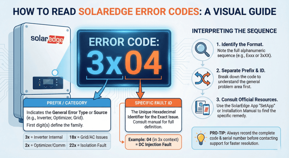
SolarEdge inverter error codes indicate specific system malfunctions requiring immediate diagnosis and appropriate response. When your SolarEdge inverter displays fault codes like 18xB7, 18xC, 03x9a, or 18×75, understanding their meanings determines whether simple resets resolve issues or professional repair services become necessary.
Common SolarEdge inverter problems include:
- Grid voltage errors (18×37, 18×38): Typically safe to reset after grid stabilizes
- Arc fault detection (18xC): Never reset; requires professional investigation
- Isolation faults (03x9a, 18×86): Indicates dangerous ground current leakage
- Thermal shutdown (18×75): Allow cooling period before restart
- HD-Wave capacitor failures (18xB5, 18xB7): Affects 2017-Q2 2018 models, requires warranty replacement
This comprehensive troubleshooting guide covers SolarEdge error code definitions, safe reset procedures, model-specific issues (HD-Wave, StorEdge, and commercial three-phase), isolation fault testing with acceptable resistance values (200 MΩ for cables, 600 kΩ for single-phase strings, and 1 MΩ for three-phase), arc fault investigation protocols, grid-related troubleshooting, advanced monitoring platform features, and when professional solar repair services become necessary.
Quick reference: A blinking green light means normal operation; a red light signals fault conditions. Always document error codes before resetting. Standard SolarEdge inverters include 12-year warranty coverage with extension options to 25 years.

Typical SolarEdge Inverter Malfunctions
System owners typically detect inverter problems when electricity generation drops below normal levels. Warning signs include:
⚠️ Reduced solar energy output or unexpected system failures
🔴 Orange or red indicator lights illuminated on the inverter
📱 Fault condition notifications appearing in the SolarEdge monitoring application
The blinking green light on SolarEdge inverters raises frequent questions. A flashing green LED normally confirms proper inverter operation and active AC power conversion. Blink frequency relates directly to power output levels; rapid flashing indicates maximum production. Steady green illumination also represents normal functionality, whereas red LED activation typically requires fault investigation.
Red indicator lights, system shutdowns, or app notifications commonly connect to specific SolarEdge inverter error codes or fault messages. These diagnostic codes identify root causes including grid voltage instability, isolation failures, or thermal issues. Recognizing fault code meanings represents the initial step in effective SolarEdge inverter troubleshooting and determining whether simple system resets resolve issues or professional technical service proves necessary.

Decoding SolarEdge Error Codes
Diagnostic codes and flashing indicators on your inverter provide critical information about system malfunctions that impact both performance and safety.
Interpreting Fault Code Messages
Warning flashes or operational failures on your inverter typically communicate through SolarEdge diagnostic codes. These numerical indicators represent your inverter’s internal diagnostic system identifying specific malfunctions, including insulation breakdowns, arc detection events, or thermal overload conditions.
Examples include:
- Grounding or electrical wiring issues frequently trigger isolation fault codes (such as SolarEdge error code 03x9a).
- Arc fault detection codes (like error code 18xC) signal potentially hazardous electrical arcing requiring urgent intervention.
- Thermal overload warnings (including SolarEdge fault code 18×75) confirm the inverter has exceeded safe operating temperatures and requires cooldown periods before restart attempts.
Monitoring these SolarEdge error codes helps you determine whether problems qualify as minor issues suitable for user-level resets or critical malfunctions demanding professional solar repair services or SolarEdge customer support intervention.
Note: Document the SolarEdge error code through screenshots or written records before initiating system resets. This documentation enables SolarEdge customer service or professional solar repair technicians to diagnose problems more efficiently.
When uncertainty exists regarding reset procedures or specific SolarEdge inverter error code meanings, SolarEdge offers comprehensive fault code documentation within its monitoring application and support website. For complex malfunctions or situations where original installation companies have ceased operations, professional solar repair services can safely restore your system to full operational status.

SolarEdge Inverter Indicator Light Interpretation
LED indicators on the inverter deliver rapid visual confirmation of operational status. Not every SolarEdge inverter model includes indicator lights, though many units feature them, particularly older models and various current residential configurations.
Safe SolarEdge Inverter Reset Procedures
Temporary SolarEdge inverter malfunctions, including grid instabilities or thermal issues, sometimes resolve through basic reset procedures. Follow this reset protocol:
- Deactivate the AC disconnect switch (located near your primary electrical panel or utility meter).
- Deactivate the DC disconnect switch (positioned on the inverter or adjacent to the solar array).
- Allow a minimum 5-minute waiting period for complete inverter power discharge.
- Reactivate the DC disconnect switch.
- Reactivate the AC disconnect switch.
- Monitor the inverter reboot process until status indicators stabilize.
Appropriate Reset Scenarios:
- Excessive or insufficient grid voltage conditions (codes including 18×38, 18×37).
- Thermal shutdown events (18×75) following adequate cooling periods.
⚠️ Critical Reset Restrictions:
Arc fault detection (18xC), isolation failures (03x9a, 18×86), or ground current malfunctions (18x3D). These SolarEdge fault codes indicate severe problems requiring professional technical intervention.
Solar Permit Solutions
Need Solar Permit Plans?
Professional, permit-ready solar plan sets delivered fast. Residential and commercial projects across all 50 states.
Locating SolarEdge Error Code Reference Information
Identifying specific alert meanings proves essential when addressing SolarEdge inverter malfunctions. Multiple reliable sources exist for interpreting SolarEdge error messages and understanding system diagnostic communications.
SolarEdge Fault Code Decoding Resources
- SolarEdge inverter manual: Contains fault code listings and fundamental troubleshooting guidance, with model-specific documentation.
- SolarEdge support portal: The manufacturer’s website provides searchable knowledge databases featuring current code definitions and procedural instructions.
- SolarEdge monitoring app guide: Fault code appearances in the application typically include brief issue descriptions covering optimizer malfunctions, firmware problems, or voltage warnings. Urgent problem notifications are delivered through system alerts.
- SolarEdge Users’ Facebook Community: Peer support and guidance from fellow SolarEdge system owners, serving as alternative resources when manufacturer customer support proves insufficient for troubleshooting needs.
Utilizing these resources clarifies SolarEdge error code meanings and determines whether self-resolution remains possible or professional assistance becomes necessary.
Grid-Related Error Codes and Utility Issues
Grid voltage and frequency errors represent common SolarEdge inverter fault codes that homeowners encounter. Understanding these utility-related problems helps determine whether issues originate from your solar system or the electrical grid.
Grid Voltage and Frequency Error Codes
Common Grid-Related Fault Codes:
- Error Code 18×37: Grid voltage below acceptable limits
- Error Code 18×38: Grid voltage exceeds acceptable parameters
- High/Low Grid Voltage Faults: Inverter detects voltage outside safe operating ranges
These SolarEdge error codes typically trigger automatic inverter shutdowns protecting equipment from grid instabilities. Once grid conditions normalize, inverters generally restart automatically following reconnection delay periods mandated by safety standards.
Determining Utility vs. System Problems
Contact Your Utility Company When:
- Multiple neighbors experience simultaneous power quality issues
- Voltage fluctuations occur during specific times (peak demand periods)
- Recent utility infrastructure work happened in your area
- Error codes persist across multiple days despite normal weather conditions
- Grid frequency variations appear in monitoring data
Address as System-Level Problem When:
- Only your inverter displays fault codes while neighbors’ systems operate normally
- Physical damage exists to your service entrance or meter equipment
- Recent electrical work occurred at your property
- AC disconnect or circuit breaker issues present themselves
- Wiring modifications happened between the inverter and utility interconnection
Country Settings and Grid Protection Values
SolarEdge inverters include programmable country-specific settings, ensuring compliance with regional grid codes. Incorrect country configuration triggers persistent voltage and frequency error codes even when grid conditions remain normal.
Verifying Country Settings:
- Access inverter setup mode through LCD display or SetApp configuration tool
- Navigate to grid protection parameter settings
- Confirm country selection matches your installation location
- Verify grid protection values align with local utility requirements
Note: Modifying grid protection values requires installer-level access and should only occur when permitted by local authorities and utility interconnection agreements.
Phase Balance Issues in Commercial Systems
Commercial three-phase SolarEdge inverters monitor voltage balance across all three phases. Significant imbalances trigger protective shutdowns preventing equipment damage.
Phase Balance Troubleshooting:
- Verify balanced load distribution across three-phase service
- Check for loose connections at AC terminal blocks
- Measure voltage on each phase at inverter AC output
- Review phase balance settings in inverter configuration (Enable/Disable options available)
- Contact utility if phase voltage differences exceed acceptable tolerances
IEEE 1547 and Rule 21 Compliance Troubleshooting
Modern SolarEdge inverters include IEEE1547 and California Rule 21 compliance certifications requiring specific grid support functions and voltage/frequency ride-through capabilities.
Compliance-Related Error Resolution:
- Confirm inverter firmware version supports current IEEE1547 standards
- Verify Rule 21 phase 3 settings if operating in California
- Review utility interconnection agreement requirements
- Check advanced inverter function settings (voltage support, frequency response)
- Document grid events occurring during fault conditions for utility coordination
When Grid Events Trigger Repeated Shutdowns:
Contact both your utility provider and solar support services. Grid-side issues, including voltage sags, swells, or harmonic distortion, may require utility intervention, while inverter sensitivity settings might need professional adjustment to prevent nuisance tripping.

Isolation Fault Troubleshooting
Isolation faults indicate DC current leakage to ground (protective earth), creating safety hazards requiring immediate investigation. SolarEdge error codes 03x9a and 18×86 signal isolation resistance below acceptable thresholds.
Understanding Isolation Faults
Common Causes:
- Module insulation degradation from moisture ingress
- Damaged or abraded DC cables exposing conductors
- Defective power optimizers with internal insulation breakdown
- Inverter internal component failures
- Improper grounding or bonding installations per NEC requirements
Step-by-Step Insulation Resistance Testing
Required Equipment:
- Insulation resistance tester (megohmmeter)
- Connector branch cables for optimizer testing
- Multimeter for voltage verification
- Personal protective equipment
Testing Procedure:
1. System Shutdown:
- Set inverter P/I/O switch to OFF position
- Wait minimum 5 minutes for DC voltage reduction below 50V
- Verify voltage safety using multimeter
- Maintain DC isolation switch in ON position (if installed separately)
2. Initial Inverter Test:
- Disconnect all DC strings from inverter inputs
- Test insulation resistance between DC positive bus and ground
- Test insulation resistance between DC negative bus and ground
- Record measurements for baseline reference
3. Individual String Testing:
- Reconnect one string to inverter
- Set inverter switch to ON and monitor for fault recurrence
- If fault appears, this string contains the problem
- If no fault, turn OFF and test next string
- Continue until faulty string identified per NEC 690.7 voltage requirements
String-by-String Isolation Procedures
Once the problematic string is identified, systematic component testing isolates the specific failure point.
String Segment Testing:
1. Cable Insulation Testing:
- Disconnect string from inverter
- Test cable insulation resistance: positive to ground, negative to ground
- Use insulation tester set to appropriate voltage (typically 500-1000V DC)
- Acceptable reading: 200MΩ or greater for cables
2. String Assembly Testing:
- Connect string and test total insulation resistance
- Test from positive to ground and negative to ground
- Acceptable reading: 600kΩ minimum for single-phase inverters, 1MΩ minimum for three-phase inverters
- If readings fall below thresholds, proceed to individual component testing
3. Power Optimizer and Module Testing:
- Disconnect suspect optimizers from string
- Test individual optimizer insulation resistance using branch cables
- Connect positive probe to optimizer positive terminal, negative probe to ground
- Repeat for optimizer negative terminal to ground
- If optimizer resistance is less than 200MΩ, component replacement required
4. Module Isolation Testing:
- Disconnect modules from optimizers
- Test module insulation resistance positive to frame and negative to frame
- Compare suspect module readings against known good modules
- Consult module manufacturer specifications for acceptable resistance values
Acceptable Resistance Values
Industry Standard Thresholds (Per SolarEdge Documentation):
- DC Cables: Minimum 200MΩ insulation resistance
- String Assembly (Single-Phase Inverters): Minimum 600kΩ
- String Assembly (Three-Phase Inverters): Minimum 1MΩ
- Component-Level Testing: Readings below 200MΩ typically indicate component failure
Important: Resistance values within 10% of fault thresholds may indicate developing problems. Consider waiting for better weather conditions (moisture can temporarily lower readings) or scheduling preventive component replacement.
Arc Fault Detection and Response
Arc fault detection protects against potentially dangerous electrical arcing that can cause fires or equipment damage. SolarEdge error code 18xC signals arc fault detection activation.
What Causes Arc Faults
Primary Arc Fault Sources:
1. Connection Issues:
- Loose MC4 or other DC connectors
- Improperly crimped terminals
- Corroded connection points
- Vibration-induced connector separation
- Thermal cycling causing connection degradation
2. Cable Damage:
- Physical damage from installation traffic
- Animal damage (rodent chewing)
- UV degradation of cable jackets
- Sharp edge abrasion during installation
- Staple or fastener penetration
3. Component Failures:
- Optimizer internal component breakdown
- Module junction box failures
- Combiner box terminal deterioration
- Damaged blocking diodes (if present)
Why You Should NEVER Reset Arc Faults
Arc fault detection represents critical safety protection. Resetting arc fault errors without identifying and correcting the underlying cause creates severe risks:
Safety Hazards from Improper Arc Fault Resets:
- Fire Risk: Continued arcing generates extreme heat igniting surrounding materials
- Equipment Damage: Arcing degrades conductors and components progressively
- Electric Shock: Arc locations may create exposed energized conductors
- Code Violations: Overriding safety systems violates NEC requirements
- Warranty Voidance: Improper arc fault handling may void equipment warranties
- Liability Issues: Ignoring arc faults creates legal liability for resulting damages
National Electrical Code Requirements:
NEC Article 690.11 mandates arc-fault protection for PV systems per UL 1741 inverter safety standards. Disabling or circumventing these protections violates electrical code and creates unsafe installations.
Proper Arc Fault Investigation Procedures
Systematic Arc Fault Resolution:
1. Initial Assessment:
- Document exact error code and occurrence timestamp
- Note weather conditions during fault event
- Check for visible damage, burning odors, or discoloration
- Review system layout identifying accessible connection points
- DO NOT attempt reset before completing investigation
2. Visual Inspection Protocol:
- Examine all accessible DC connectors for proper mating
- Inspect cable routing for sharp edges or pinch points
- Check optimizer enclosures for damage or moisture ingress
- Review module junction boxes for signs of arcing (burn marks, melted components)
- Photograph any anomalies for documentation
3. Connection Verification:
- Power down system following proper safety procedures
- Verify DC voltage reaches safe levels before touching conductors
- Disconnect and inspect each MC4 connector pair
- Check for proper connector engagement (audible click)
- Examine contact surfaces for pitting, discoloration, or corrosion
- Clean contacts if contamination present (approved contact cleaner only)
- Re-mate connections ensuring full engagement
4. Resistance Testing:
- Use multimeter to test DC circuit continuity
- Measure resistance across connection points
- Elevated resistance indicates poor connections requiring correction
- Compare readings across multiple connection points for consistency
5. Thermal Imaging (If Available):
- Energize system briefly under supervision
- Use infrared camera to identify hot spots
- Elevated temperatures indicate high-resistance connections
- Document thermal anomalies for repair prioritization
6. Professional Service Requirements:
Contact qualified solar technicians immediately if:
- Arc source cannot be clearly identified
- Multiple arc fault events occur
- Visible damage exists to electrical components
- Burning odors persist after visual inspection
- System complexity exceeds homeowner capability
- Arc fault occurs in inaccessible locations (rooftop arrays)
Post-Repair Verification:
After correcting identified issues:
- Restore system to operational status
- Monitor for 24-48 hours confirming fault elimination
- Review monitoring data for recurring error codes
- Document repairs completed and components replaced
- Update system maintenance records
Arc fault protection exists to prevent catastrophic failures. Always treat arc fault errors as serious safety events requiring thorough investigation before system restoration.
Model-Specific Troubleshooting Guide
Different SolarEdge inverter models feature unique characteristics, common failure modes, and troubleshooting procedures. Understanding model-specific issues enables more effective diagnosis and resolution.
HD-Wave Inverter-Specific Issues
HD-Wave technology inverters introduced revolutionary efficiency improvements but early production models experienced specific component reliability challenges.
Common HD-Wave Error Codes:
Error Code 18xB5 (DC/AC In-Stage Overvoltage):
- Official Description: DC/AC in-stage overvoltage (user displays may show “Vcap11 Surge”)
- Cause: Component failure in DC-to-DC conversion stage, often related to defective capacitors
- Models Affected: Primarily SE7600H-US and SE10000H-US manufactured 2017-Q2 2018
- Symptoms: Inverter enters continuous reboot cycle, no sustained operation
- Resolution: Component replacement or complete inverter replacement under warranty
- Note: Known manufacturing defect affecting early HD-Wave production runs
Error Code 18xB7 (DC/AC In-Stage Overvoltage):
- Official Description: DC/AC in-stage overvoltage
- Cause: Failed capacitor components in power conversion circuit
- Models Affected: Multiple HD-Wave models from 2017-Q2 2018 production
- Symptoms: Intermittent operation, sudden shutdown during peak production, continuous reboot loops
- Resolution: Warranty replacement typically required
- Manufacturer Response: SolarEdge acknowledged component quality issues related to defective capacitor supplier during this production period
HD-Wave Capacitor Failure Recognition:
If your HD-Wave inverter manufactured between 2017 and Q2 2018 displays 18xB5 or 18xB7 error codes:
- Document inverter model and serial number
- Record error code and occurrence frequency
- Contact SolarEdge technical support for warranty evaluation
- Reference known capacitor issue when opening support case
- Request expedited warranty processing given known defect status
HD-Wave Reset Procedures (LCD Display Models):
HD-Wave inverters with LCD screens follow specific reset protocols:
- Access inverter LCD display panel
- Verify current error code display
- Turn AC disconnect OFF
- Turn DC disconnect or inverter switch to OFF (0 position)
- Wait for LCD display showing voltage reduction (target <50V)
- Minimum 5-minute waiting period
- Turn DC disconnect or switch to ON (I position)
- Turn AC disconnect ON
- Monitor LCD during reboot sequence
- Verify normal status screens appear without error codes
Commercial Three-Phase Inverter Troubleshooting
Commercial smart solar inverters feature different architectures, error codes, and troubleshooting approaches compared to residential single-phase models.
Three-Phase Specific Error Codes:
Commercial inverters generate distinct fault codes addressing:
- Individual phase voltage/current imbalances
- Three-phase synchronization issues
- Higher-power thermal management problems
- Advanced grid support function faults
- Multi-string input management errors
Synergy Technology Considerations:
Commercial inverters utilizing Synergy technology enable multiple inverter paralleling:
- Master/follower communication errors
- Synergy bus connection faults
- Load sharing imbalance issues
- Coordinated shutdown events
Three-Phase Troubleshooting Priorities:
1. Verify Phase Balance:
- Measure voltage on L1, L2, L3 terminals
- Check current balance across phases
- Review utility service for pre-existing imbalances
- Disable phase balance monitoring if permitted (commercial applications)
2. Check Three-Phase Connections:
- Verify proper L1, L2, L3 terminal assignments
- Confirm neutral and ground connections
- Inspect AC terminal torque specifications
- Test for loose connections causing phase-specific errors
3. Review Commercial-Specific Settings:
- Export limitation configurations
- Demand response settings
- Grid support function parameters
- Communication with facility energy management systems
StorEdge and Battery Integration Issues
StorEdge inverters integrating battery storage systems present unique troubleshooting challenges beyond standard grid-tied inverters.
Common StorEdge Error Scenarios:
Battery Communication Failures:
- The inverter cannot detect connected battery
- Intermittent battery communication loss
- Battery parameter mismatches
- Firmware compatibility issues between inverter and battery
Backup Mode Malfunctions:
- Backup Interface not responding
- Automatic transfer switch errors
- Critical loads not powered during grid outages
- Battery not charging despite available solar production
DC-Coupled Battery Troubleshooting:
1. Verify Battery Connections:
- Check battery DC connections at inverter terminals
- Confirm battery breaker/disconnect status
- Test battery voltage levels
- Review battery BMS (Battery Management System) status
2. Communication Verification:
- Check RS485 or CAN communication cables
- Verify communication termination resistors
- Review inverter battery configuration settings
- Confirm battery firmware version compatibility
3. Backup System Testing:
- Test backup transition by simulating grid outage
- Verify critical loads panel energization
- Check backup power capacity matches expectations
- Review generator integration (if applicable)
Model-Specific Reset Procedures
LCD Display Models (HD-Wave, Some Commercial):
Follow standard reset procedure with LCD voltage monitoring:
- Wait for “VDC: XX.X” display showing <50V
- Document any error codes appearing during shutdown
- Monitor status screens during reboot
- Verify P_OK count matches installed optimizer quantity
Non-LCD Models (SetApp-Only Configuration):
Models without LCD displays require alternative monitoring:
- Use SetApp mobile application for status monitoring
- Rely on LED indicator patterns during reset
- Allow extended reboot time without visual confirmation
- Verify operation through monitoring portal after restart
Three-Phase Commercial Models:
Additional considerations for commercial three-phase resets:
- Coordinate with facility electrical operations
- Verify three-phase disconnect procedures
- Allow longer stabilization periods after restart
- Monitor three-phase voltage balance during energization
- Document grid conditions during reset procedure
Understanding model-specific characteristics enables targeted troubleshooting approaches, reducing diagnostic time and improving resolution success rates.
Warranty Coverage, Repair Services & Professional Support Timing
Standard SolarEdge inverters include 12-year limited warranty protection, featuring extension options reaching 20-25 years. This coverage addresses numerous hardware malfunctions triggering SolarEdge error codes.
Fault code displays or blinking green light patterns on your SolarEdge inverter may require attention. Understanding common SolarEdge error codes, appropriate reset timing, and service call necessity supports effective troubleshooting, warranty claim processing, or complete inverter replacement requirements.
🚨 Persistent SolarEdge inverter fault codes demand immediate attention. Continued operation despite power generation may accelerate equipment degradation, reduce system efficiency, and generate safety risks.
⚠️ SolarEdge Fault Code Reset Restrictions
Certain SolarEdge inverter fault codes signal critical problems, including ground faults, arc detection events, or hardware component failures. Reset attempts in these situations may temporarily eliminate error messages without addressing fundamental issues, potentially worsening conditions progressively.
Avoid Inverter Reset Attempts When:
- Recurring codes appear, such as SolarEdge fault code 33x (ground/insulation malfunction)
- Burning odors or abnormal sounds emanate from the inverter
- The inverter experiences repeated shutdowns following each reset attempt
- SolarEdge monitoring application displays continuous alerts after reboot procedures
When uncertainty exists regarding SolarEdge inverter error code resolution or unsuccessful reset attempts have occurred, qualified technician contact becomes advisable.
Accessing SolarEdge Support for Inverter Troubleshooting and Warranty Assistance
When confronting SolarEdge inverter malfunctions, the manufacturer provides multiple diagnostic tools enabling homeowners to identify, monitor, and resolve system issues. From From SolarEdge inverter fault code verification to warranty coverage confirmation, the manufacturer’s platform simplifies information access and facilitates timely action.
Utilizing the SolarEdge Monitoring App for Inverter Error Code Tracking
The SolarEdge monitoring application represents one of the most powerful diagnostic instruments for identifying and monitoring SolarEdge inverter malfunctions. Application setup proves highly advisable, particularly when SolarEdge error codes appear or system performance degradation occurs.
Application capabilities include:
- Live system status verification: The application displays current energy production levels and identifies malfunctioning modules.
- SolarEdge inverter fault code display: Problem detection by your inverter typically generates summary or comprehensive error messages within the application.
- Inverter history monitoring: Track production trends, historical fault records, and performance metrics over extended periods.
- Automated alert reception: The application delivers automatic notifications when conditions change, including inverter communication failures or module underperformance.
For enhanced SolarEdge monitoring app assistance, the manufacturer’s website features user documentation and video tutorials explaining system view navigation, error message interpretation, and alert configuration for choosing the right solar inverter system.
Verifying SolarEdge Inverter Warranty Coverage Following Fault Detection
When SolarEdge inverter fault codes indicate hardware component failures or inverters fail to recover following reset procedures, warranty coverage verification becomes appropriate. Standard SolarEdge inverters include 12-year limited warranty protection, with certain models offering optional extensions or supplementary coverage when integrated with panel-level systems.
SolarEdge Warranty Status Confirmation Steps:
- Identify your inverter’s serial number: This identifier typically appears on labels affixed to the inverter’s exterior panel.
- Access the SolarEdge warranty lookup page to verify whether your unit remains within warranty coverage periods using the serial number.
- Verify system registration status: Certified partner installations may include pre-completed registration, though confirmation or detail updates remain possible through your SolarEdge monitoring account.
- Assemble warranty claim documentation: Required information includes the inverter serial number, installation date, and problem description (incorporating any SolarEdge error codes displayed on the application or inverter screen).
The manufacturer’s support website provides detailed claim submission guidance and direct technical team contact information. When warranty process completion proves challenging or installation contractors remain unavailable, professional U.S. solar repair services can restore system functionality.

Advanced SolarEdge Monitoring Platform Features
Beyond basic fault code displays, the SolarEdge monitoring platform delivers comprehensive diagnostic capabilities enabling detailed system analysis and proactive maintenance according to renewable energy best practices from the Department of Energy.
Module-Level Data Interpretation (CPU Version 3.1808+)
Inverters operating CPU firmware version 3.1808 or higher provide individual module performance data accessible through monitoring interfaces.
Accessing Module-Level Information:
- Navigate to Layout tab in monitoring portal
- Select individual modules to view real-time performance metrics
- Compare module output voltages and current levels
- Identify underperforming modules through comparative analysis
- Review module temperature data when available
Key Module Metrics:
- Voltage Output: Individual module voltage under current operating conditions
- Current Production: Instantaneous current generation per module
- Power Production: Real-time wattage output compared to expected performance
- Temperature Readings: Module operating temperatures affecting performance
Using Logical Layout for Diagnostic Analysis
The logical layout view displays system architecture showing electrical connectivity between inverters, strings, and individual modules.
Diagnostic Applications:
- Identify which modules connect to specific inverter inputs
- Trace string configurations for troubleshooting non-communicating optimizers
- Verify system topology matches physical installation
- Locate position of faulty components within array architecture
- Update layout after optimizer or module replacements
Layout Verification Steps:
- Access Admin section and select Logical Layout
- Compare displayed configuration against installation documentation
- Update serial numbers when replacing optimizers
- Verify string assignments match physical wiring
- Confirm module counts align with P_OK display readings
Reading Power Curves to Identify Clipping and Underperformance
Inverter power curve analysis reveals performance issues, including AC clipping, DC voltage problems, and production losses.
Power Curve Interpretation:
Normal Operation Indicators:
- Smooth bell-shaped curve following solar irradiance patterns
- Peak production occurring during midday hours
- Gradual power increase in the morning and decrease in the afternoon
- Consistent day-to-day curve shapes under similar weather conditions
Clipping Identification:
- Flat-topped power curves during peak production hours
- AC power output plateaus at the inverter’s maximum rating
- DC voltage remains elevated while AC power caps
- Potential solutions: Inverter upsizing or array reconfiguration
Underperformance Signals:
- Scattered or erratic power production despite clear weather
- Lower peak output compared to historical performance
- Sudden production drops indicating potential failures
- String-level issues visible through uneven DC voltage readings
Remote Troubleshooting Techniques
The monitoring platform enables remote system diagnostics, reducing on-site service call requirements developed by organizations like the National Renewable Energy Laboratory.
Remote Diagnostic Procedures:
1. Communication Verification:
- Confirm inverter reporting status in equipment list
- Check last communication timestamp
- Verify internet connectivity through gateway status
- Review communication method (Ethernet, WiFi, cellular)
2. Error Log Analysis:
- Access inverter error history tab
- Document error code patterns and frequencies
- Identify recurring faults suggesting systemic problems
- Compare error timing against weather events or grid disturbances
3. Performance Comparison:
- Compare production across multiple inverters on same site
- Analyze specific inverter underperformance relative to site average
- Review optimizer-level data for string-specific issues
- Check for shading patterns affecting particular array sections
4. Configuration Review:
- Verify inverter settings match installation specifications
- Confirm power optimizer counts match P_OK readings
- Check communication settings and network configurations
- Review energy management settings if applicable
Alert Prioritization and Severity Indicators
The monitoring platform categorizes alerts by severity, enabling appropriate response prioritization.
Alert Severity Levels:
Critical Alerts (Immediate Action Required):
- System complete shutdown events
- Arc fault detection activation
- Isolation fault conditions
- Ground current surge errors
- Hardware component failures
Warning Alerts (Monitor and Schedule Service):
- Single optimizer communication losses
- Temporary grid voltage fluctuations
- Minor temperature warnings
- Communication interruptions resolving automatically
Informational Alerts (Awareness Only):
- Night mode transitions
- Scheduled maintenance reminders
- Firmware update availability notifications
- Performance report generation confirmations
Alert Response Strategies:
- Configure notification preferences for different alert types
- Establish escalation procedures for critical fault conditions
- Document alert patterns indicating developing problems
- Schedule preventive maintenance based on warning alert trends
- Integrate alerts with facility energy management systems for commercial installations
When Professional Solar Repair Services Become Necessary for SolarEdge Inverter Troubleshooting
Basic reset procedures or monitoring app fault code reviews resolve certain SolarEdge inverter malfunctions. However, persistent system failures or absent installer support require professional intervention. Qualified solar repair technicians address complex problems ranging from SolarEdge inverter troubleshooting to comprehensive system diagnostics.
Managing Orphaned SolarEdge Systems
Original installer business closures or unresponsive service departments create orphaned SolarEdge system situations. This circumstance occurs more frequently than homeowners anticipate, particularly as solar industry consolidation continues. Without installer support access, obtaining assistance for persistent SolarEdge inverter fault codes or warranty claim processing becomes challenging.
Red status indicator lights or monitoring application alerts require immediate attention; these warning signals indicate serious problems potentially reducing system efficiency or causing permanent equipment damage. When support resources remain unclear, establishing connections with trusted repair providers becomes essential.
Conclusion
SolarEdge inverter troubleshooting requires understanding diagnostic codes, recognizing model-specific issues, and knowing when professional intervention becomes necessary. Whether addressing grid voltage fluctuations, isolation faults, arc detection events, or model-specific capacitor failures in early HD-Wave units, systematic troubleshooting approaches accelerate problem resolution and minimize system downtime.
Document all error codes before attempting resets, utilize the SolarEdge monitoring platform for remote diagnostics, and never bypass critical safety protections like arc fault detection. While basic resets resolve temporary grid instabilities or thermal shutdowns, persistent fault codes, particularly isolation errors, arc faults, or hardware failures, demand immediate professional evaluation.
For orphaned systems lacking installer support, professional solar repair services provide essential troubleshooting assistance, warranty claim processing, and equipment replacement coordination. Regular monitoring platform reviews, proactive alert response, and understanding your specific inverter model’s characteristics ensure optimal system performance and longevity according to industry standards and certifications from IREC.
FAQs
Need Solar Permit Plans?
Professional, permit-ready solar plan sets delivered fast. Residential and commercial projects across all 50 states.
Frequently Asked Questions
A blinking green light on your SolarEdge inverter indicates normal operation with active AC power generation. The blink frequency corresponds directly to power output levels; rapid flashing signals maximum production, while slower blinking indicates lower output. A steady green light also confirms normal functionality. Red LED activation requires immediate investigation as it signals fault conditions requiring troubleshooting.
To safely reset your SolarEdge inverter, first document the error code through screenshots. Then turn OFF the AC disconnect switch, followed by the DC disconnect switch. Wait minimum 5 minutes for complete voltage discharge below 50V. Reactivate the DC disconnect first, then the AC disconnect. Monitor status lights during reboot. Never reset arc fault codes (18xC), isolation faults (03x9a, 18x86), or ground current errors (18x3D); these require professional service following NEC 690.12 rapid shutdown requirements.
Error code 18xB7 (DC/AC in-stage overvoltage) on HD-Wave inverters typically indicates capacitor component failures, particularly in SE7600H-US, SE10000H-US, and SE5000H-US models manufactured between Q4 2017 through Q2 2018. This hardware error stems from defective capacitors supplied during this production period. SolarEdge changed capacitor suppliers in Q2/Q3 2018, improving reliability in later models. Contact SolarEdge support immediately for warranty replacement evaluation.
Grid-related problems typically affect multiple neighbors simultaneously, occur during peak demand periods, or follow recent utility infrastructure work. System-level faults appear only on your inverter while neighbors' systems operate normally. Check for physical damage to service entrance equipment, recent property electrical work, or AC disconnect issues. Grid voltage error codes (18x37, 18x38) may originate from utility-side instabilities requiring coordination with your power company and proper understanding of solar engineering requirements for permits.
Repeated shutdowns after reset attempts indicate serious underlying problems requiring professional diagnosis. Document shutdown frequency, error codes displayed, and conditions when failures occur (time of day, weather, production levels). Check for burning odors, unusual sounds, or physical damage. Never continue resetting when arc faults, isolation errors, or ground current faults appear. Contact qualified solar technicians for comprehensive system diagnostics, especially if your original installer is unavailable or the system qualifies as orphaned. Understanding proper solar conductor sizing per NEC standards and following proper safety code requirements helps ensure proper system operation per SEIA industry standards.
SPS Editorial Team
Solar Permit Solutions
Solar Permit Solutions provides professional solar permit design services for residential, commercial, and off-grid installations across all 50 states. Our team ensures permit-ready plan sets delivered fast.
Related Articles

Utility Interconnection Requirements for Solar Installers: The 6 Rules Every Utility Enforces
interconnection agreement, UL 1741 and IEEE 1547 certified inverters, a utility-...

How to Respond to Solar Permit Corrections (And Get Approved on Resubmission)
To respond to a solar permit correction, read every comment from every reviewing...

Can an EV Charging Station Be Powered by Solar? Here’s How to Build One
Yes, an EV charging station can be powered by solar. A grid-tied solar array pai...