SolarEdge SE50KUS Inverter Overview
The SolarEdge SE50KUS is a 50kW three-phase commercial solar inverter with these specifications:
- Power Output: 50kW at 208V, 97% CEC efficiency
- Technology: Synergy modular design (3 units + 1 manager)
- DC Input: 87,500W max, 370-600V range, 12 string inputs
- Safety Features: Built-in rapid shutdown (NEC 690.12), arc fault (UL1699B), 1A GFDI
- Certifications: UL1741 SA/SB, IEEE 1547-2018, California Rule 21
- Weight: 70.4 lbs per Synergy Unit, 39.6 lbs Synergy Manager
- Warranty: 12 years (extendable to 20)
The SE50KUS is designed for commercial rooftop and ground-mount installations requiring three-phase 208V interconnection. Its Synergy Technology allows each unit to operate independently, providing higher system uptime and enabling two-person installation due to the reduced weight of individual components. Our commercial solar design services team has extensive experience with Synergy Technology inverters. You can download the complete technical specifications from the official SolarEdge SE50KUS datasheet.
This guide covers complete permit documentation requirements, NEC code compliance details, plan set specifications, and installation best practices extracted from the SolarEdge Synergy Technology installation manual.

Why the SE50KUS Matters for Commercial Solar Projects
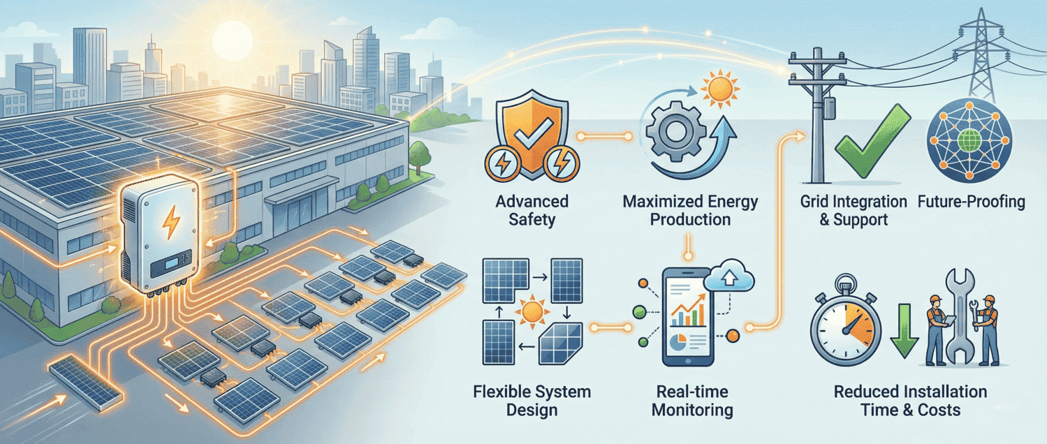
Getting a commercial solar permit approved often comes down to one critical factor: accurate inverter documentation. The SolarEdge SE50KUS has become a go-to choice for 50kW commercial installations because its modular Synergy Technology design, combined with built-in safety features and comprehensive certifications, makes it one of the most permit-friendly commercial inverters on the market. Unlike residential systems that use microinverters, commercial projects require three-phase inverters for commercial installations to handle substantial power loads efficiently.
From a code compliance perspective, the SE50KUS comes pre-equipped with built-in rapid shutdown functionality compliant with NEC Article 690 (2014-2023), integrated arc fault protection per UL1699B, and certifications including UL 1741 SA/SB for advanced grid support functions. These built-in features significantly reduce the complexity of permit documentation. For a detailed comparison of inverter technologies, see our string inverter vs microinverter guide.
Technical Specifications for Permit Documentation
The following specifications are extracted directly from SolarEdge’s official SE50KUS datasheet. These values should be referenced in your solar plan sets and permit applications. For the most current specifications, always verify against the California Energy Commission Solar Equipment Lists.
AC Output Specifications
These output specifications are essential for single-line diagrams and electrical load calculations:
- Rated AC Active Output Power: 50,000W
- Maximum AC Apparent Output Power: 50,000VA
- AC Output Voltage (Line-to-Line): 183V minimum, 208V nominal, 229V maximum
- AC Output Voltage (Line-to-Neutral): 105V minimum, 120V nominal, 132.5V maximum
- AC Output Line Connections: 3W + PE or 4W + PE
- Supported Grid Configurations: WYE (TN-C, TN-S, TN-C-S, TT, IT) and Delta IT
- AC Frequency Range: 59.5Hz minimum, 60Hz nominal, 60.5Hz maximum
- Maximum Continuous Output Current (per phase): 139.5A at unity power factor
- Power Factor Range: ±0.85 to 1.0
- Total Harmonic Distortion: ≤3%
- CEC Weighted Efficiency: 97%
- GFDI Threshold: 1A
DC Input Specifications
These input specifications are critical for string sizing calculations and DC wiring design:
- Maximum DC Power (Module STC) – Total Inverter: 87,500W
- Maximum DC Power (Module STC) – Per Synergy Unit: 29,165W
- Maximum Input Voltage (DC+ to DC-): 600Vdc
- Operating Voltage Range: 370Vdc to 600Vdc
- Maximum Input Current: 3 × 46.5Adc (139.5A total)
- DC Input Configuration (Multi-input): 12 pairs total (4 per Synergy Unit), 6-12 AWG wire
- DC Input Configuration (Combined): 3 pairs total (1 per Synergy Unit), maximum 2 AWG copper or aluminum
- Transformer-less Design: Yes, ungrounded PV array required
- Reverse Polarity Protection: Yes
- Ground-Fault Isolation Detection: 167kΩ sensitivity per Synergy Unit
Physical Specifications for Site Plans
Include these dimensions and weights in your site plan drawings and structural calculations:
- Synergy Unit Dimensions (H × W × D): 22″ × 12.9″ × 10.75″ (558 × 328 × 273 mm)
- Synergy Manager Dimensions (H × W × D): 14.17″ × 22.4″ × 11.6″ (360 × 560 × 295 mm)
- Synergy Unit Weight: 70.4 lbs (32 kg) each
- Synergy Manager Weight: 39.6 lbs (18 kg)
- Total System Weight (3 units + manager): Approximately 250 lbs (114 kg)
- Minimum Mounting Area Required: 39.68″ × 45″ (100.8 cm × 114.5 cm)
- Enclosure Rating: NEMA 3R (outdoor rated)
- Operating Temperature Range: -40°F to +140°F (-40°C to +60°C)
- Cooling Method: Fan (user replaceable)
- Noise Level: <67 dBA
- Nighttime Power Consumption: <12W

Solar Permit Solutions
Skip the Permit Headaches
We design plan sets that pass inspection the first time. Code-compliant, PE-stamped, accepted by AHJs nationwide.
Solar Permit Documentation Requirements
A complete permit package for an SE50KUS installation requires specific documentation. Understanding AHJ solar requirements helps streamline approvals. Here is what permit reviewers typically need to see:
Required Permit Documents
- Equipment Cut Sheets: Include the official SolarEdge SE50KUS datasheet showing all UL certifications. The datasheet must clearly display the UL1741, UL1741 SA, and UL1741 SB listings.
- Single-Line Diagram: Show the three-phase wye configuration with 208V nominal output. Include the DC disconnect switch location, AC breaker rating, and grounding electrode connection.
- Three-Line Diagram: Detail L1, L2, L3 phase connections with PE (protective earth) grounding per NEC Article 690 requirements.
- Site Plan: Show inverter mounting location with required clearances for heat dissipation and service access. Reference SolarEdge’s clearance guidelines application note.
- Rapid Shutdown Documentation: Document the built-in Photovoltaic Rapid Shutdown System (PVRSS) compliance per NEC 690.12. Include the required signage locations per NEC 690.56(C).
- Ground Fault Protection Details: Document the 1A GFDI threshold and isolation monitoring per NEC 690.41.
- String Sizing Calculations: Provide calculations showing string voltage within the 370V-600V operating range and compliance with maximum optimizer count (30 per string for PVRSS).
Complete your solar interconnection agreement checklist before submission. Review the solar PTO requirements and timeline for your jurisdiction to plan accordingly.
Certifications to Reference in Permit Applications
The SE50KUS holds the following certifications that should be noted in your permit documentation:
- Safety: UL1699B (arc fault), UL1741, UL1741 SA, UL1741 SB, UL1998, CSA C22.2#107.1
- Grid Connection: IEEE 1547-2018, California Rule 21, Hawaii Rule 14
- Emissions: FCC Part 15 Class A
- Canadian AFCI: According to T.I.L. M-07
- Advanced Grid Support: L/HFRT, L/HVRT, VOLT-VAR, VOLT-Watt, Frequency-Watt, Ramp Rate Control, Fixed Power Factor, Fixed Q, Cos(Phi)/Watt
Plan Set Requirements for SE50KUS Installations
Your electrical plan set must include specific wiring details extracted from the SolarEdge installation manual. Follow NEC 690.16 fuse servicing requirements for string combiner boxes. Here are the exact specifications:
AC Wiring Requirements
- Maximum AC Conduit Size: 2½ inches
- Maximum Line Conductor Size: 4/0 AWG
- Maximum PE (Ground) Conductor Size: 1/0 AWG
- AC Breaker Sizing: Based on 139.5A maximum continuous output per phase. Consult SolarEdge Application Note for specific breaker recommendations.
- Wire Configurations Supported: L1, L2, L3, PE (3-wire + ground) or L1, L2, L3, N, PE (4-wire + ground)
DC Wiring Requirements
Calculate wire sizes using our solar conductor sizing per NEC standards guide:
- Maximum DC Conduit Size: 1 × 3″ or 2 × 2″ openings
- String Input Wire Gauge (Multi-input): 6-12 AWG
- Combined Input Wire Gauge: 2-4 AWG copper or aluminum
- Homerun Cable Options: MC4 connectors (8-14 AWG) or DC terminal blocks (6-14 AWG)
- Integrated DC Fuses: 25A single pole fuses included
Surge Protection Details
- AC Surge Protection: Type II, field replaceable, integrated
- DC Surge Protection: Type II, field replaceable, integrated
- RS485 Surge Protection: Type II, field replaceable, integrated (ports 1 and 2)
- Monitoring: SPD status monitored and reported to SolarEdge Monitoring platform
String Sizing Guidelines
When calculating string configurations for the SE50KUS, use these parameters:
- Operating Voltage Window: 370V to 600V
- Maximum Power Optimizers per String: 30 (for PVRSS compliance)
- Power Optimizer Safe Voltage: 1V each when shutdown initiated
- String Verification: Total string voltage should equal 1V × number of optimizers when system is off
- Design Tool: Use SolarEdge Designer for string length verification and system validation
For larger systems exceeding panel capacity, review supply-side connection guidelines for proper interconnection methods.
Mounting Requirements
- Mounting Surface Capacity: Must support 114 kg (250 lbs) total system weight
- Vertical Mounting: Standard wall mount with provided brackets
- Horizontal Mounting: Permitted at minimum 10° tilt angle
- Salt Air Installations: Minimum 50m from shoreline; installations within 200m require SS304 stainless steel hardware (purchased separately)
- Back Support: Required when mounting on stud framing or rails to prevent wobble
NEC Code Compliance Requirements
The SE50KUS meets all solar panel safety codes including rapid shutdown, AFCI, and GFCI requirements. For comprehensive NEC guidance, refer to the IAEI’s 2023 NEC and Photovoltaic Power Systems article and the NREL IEEE 1547-2018 educational resources.
Rapid Shutdown Compliance (NEC 690.12)
The SE50KUS includes a built-in Photovoltaic Rapid Shutdown System (PVRSS) that meets NEC Article 690 requirements from 2014 through 2023. Review the 2023 NEC rapid shutdown exemptions for carport and canopy installations. Our rapid shutdown compliance roadmap details labeling and equipment requirements:
- Shutdown Initiation Methods: AC breaker OFF, DC disconnect switch OFF, or ON/OFF/P switch to OFF position
- Shutdown Time: 30 seconds maximum to reduce array conductors to safe levels
- Safe Voltage Level: Each Power Optimizer reduces output to 1V when shutdown is initiated
- Controlled Conductors: All DC and AC conductors served by power optimizers and inverters
- Required Signage (NEC 690.56(C)): “SOLAR PV SYSTEM EQUIPPED WITH RAPID SHUTDOWN” – capitalized, minimum 3/8″ height, black on yellow background
Arc Fault Protection (NEC 690.11)
The built-in AFCI meets arc fault protection per NEC 690.11 standards:
- Built-in AFCI: Certified to UL1699B standards
- Configuration: User configurable through SolarEdge SetApp mobile application
- Thermal Sensors: Built-in sensors detect faulty wiring for enhanced protection
Disconnecting Means (NEC 690.15)
Understand NEC 690.15 disconnecting means requirements for inverter isolation. The SE50KUS includes:
- DC Disconnect: Built-in per NEC 690.15 requirements
- ON/OFF/P Switch: Three-position switch for operation, shutdown, and pre-commissioning modes
- Lockable: Compliant with Section 110.25 lockout/tagout requirements
Ground Fault Protection (NEC 690.41)
- GFDI Threshold: 1A
- Isolation Detection Sensitivity: 167kΩ per Synergy Unit
- Array Configuration: Ungrounded PV array required per NEC 690.35
- Isolation Method: Inverter input and output circuits isolated from enclosure (no isolation transformer)
PV Hazard Control System (UL 3741)
When installed with compatible SolarEdge Power Optimizers, the SE50KUS forms a Listed PV Hazard Control System:
- Listing Standard: UL 3741
- Compatible Power Optimizer Input: Up to 125Vdc maximum
- Critical Requirement: Only SolarEdge Power Optimizers are compatible. Third-party equipment will void the PV hazard control system compliance.
- Worst-Case SafeDC Voltage Formula: Voc,max + (String Length – 1) × 1V

Installation Best Practices
These guidelines are extracted from the official SolarEdge installation manual to help ensure smooth permit inspections and system commissioning.
Pre-Installation Checklist
- Download SolarEdge SetApp to your mobile device before arriving at site
- Verify mounting surface can support 114 kg (250 lbs) total weight
- Prepare installation template for accurate bracket positioning
- Gather required tools: 5mm Allen screwdriver, torque wrench, wire strippers, ring terminal crimping tool
- Use SolarEdge Designer tool for system design validation before installation
- Verify all communication hardware is available (Ethernet or cellular)
Installation Sequence
Follow this sequence for proper installation:
- Install Power Optimizers first (each outputs only 1V safe voltage until inverter is ON)
- Mount Synergy Units starting with center unit first
- Mount Synergy Manager
- Connect inter-unit cables per labels on Synergy Manager
- Connect PE (ground) wire BEFORE connecting AC lines
- Connect DC strings to appropriate inputs
- Commission system using SetApp mobile application
Critical Safety Notes
- Capacitor Discharge: Wait 5 minutes after shutdown before opening inverter cover
- Installation Crew: Two-person installation required due to component weights
- Tool Restriction: Do not use impact drivers on Power Optimizers – drilling vibrations will void warranty
- Voltage Verification: Verify PV string voltage equals 1V × number of optimizers before connecting to inverter
- Torque Specifications: Cover screws 2.6 lb-ft, bracket screws 2.9 lb-ft, grounding 9.5 N*m
Pre-Commissioning (Off-Grid) Option
The SE50KUS supports pre-commissioning before grid connection for early fault detection:
- Requirements: 60W USB-C power bank with Power Delivery (20V 3A), USB-C to USB-C cable (1 meter)
- Purpose: Automated validation of system components and wiring prior to grid connection
- LED Indication: Alternating blue/green LEDs indicate ready for commissioning; alternating red/blue indicates power bank issue
- Timing: Must be performed in full daylight
Available Solar Incentives
Commercial solar installations using the SE50KUS may qualify for various federal, state, and local incentives. The Database of State Incentives for Renewables & Efficiency (DSIRE) provides the most comprehensive listing of available programs. Key incentives to research include the federal Investment Tax Credit (ITC), state rebate programs, property tax exemptions, and utility-specific incentives.
Conclusion
The SolarEdge SE50KUS represents a well-engineered solution for commercial solar installations that prioritizes both performance and code compliance. Its modular Synergy Technology design simplifies installation logistics, while built-in safety features like rapid shutdown and arc fault protection streamline permit documentation.
For installers preparing permit packages, the key advantages include comprehensive UL certifications that satisfy AHJ requirements across jurisdictions, built-in PVRSS compliance that eliminates the need for additional rapid shutdown equipment, and detailed technical specifications that translate directly into plan set documentation.
When preparing your permit application, reference the official SolarEdge datasheet and installation manual for the most current specifications. Use the SolarEdge Designer tool to validate string configurations and generate system documentation that supports your permit submission. Check the average solar permit timeline by state to plan your project schedule accordingly.
FAQs
Skip the Permit Headaches
We design plan sets that pass inspection the first time. Code-compliant, PE-stamped, accepted by AHJs nationwide.
Frequently Asked Questions
The maximum DC input power is 87,500W total at module STC conditions. This is distributed as 29,165W maximum per Synergy Unit (the inverter uses 3 Synergy Units).
The SE50KUS has 12 string inputs total (4 per Synergy Unit) in multi-input configuration. For PVRSS compliance, each string can have a maximum of 30 Power Optimizers.
Yes. The SE50KUS has built-in PVRSS (Photovoltaic Rapid Shutdown System) that complies with NEC 690.12 requirements from 2014 through 2023. When shutdown is initiated, each Power Optimizer reduces to 1V output within 30 seconds.
The SE50KUS is certified to UL1741, UL1741 SA, UL1741 SB, UL1699B (arc fault), UL1998, CSA C22.2#107.1, IEEE 1547-2018, California Rule 21, and Hawaii Rule 14. It also has FCC Part 15 Class A emissions certification.
The SE50KUS comes with a 12-year standard warranty, extendable up to 20 years. The warranty commences on the earlier of 4 months from ship date or system installation date.
Yes. The SE50KUS has a NEMA 3R enclosure rating suitable for outdoor installation. It operates in temperatures from -40°F to +140°F (-40°C to +60°C).
The AC breaker should be sized based on the maximum continuous output current of 139.5A per phase. Consult SolarEdge's Application Note for specific circuit breaker recommendations for your installation.
Yes. The SE50KUS can be mounted horizontally at a minimum tilt angle of 10°. This allows installation under or near PV modules while using them for shading.
SPS Editorial Team
Solar Permit Solutions
Solar Permit Solutions provides professional solar permit design services for residential, commercial, and off-grid installations across all 50 states. Our team ensures permit-ready plan sets delivered fast.
Related Articles

Utility Interconnection Requirements for Solar Installers: The 6 Rules Every Utility Enforces
interconnection agreement, UL 1741 and IEEE 1547 certified inverters, a utility-...

How to Respond to Solar Permit Corrections (And Get Approved on Resubmission)
To respond to a solar permit correction, read every comment from every reviewing...

Can an EV Charging Station Be Powered by Solar? Here’s How to Build One
Yes, an EV charging station can be powered by solar. A grid-tied solar array pai...