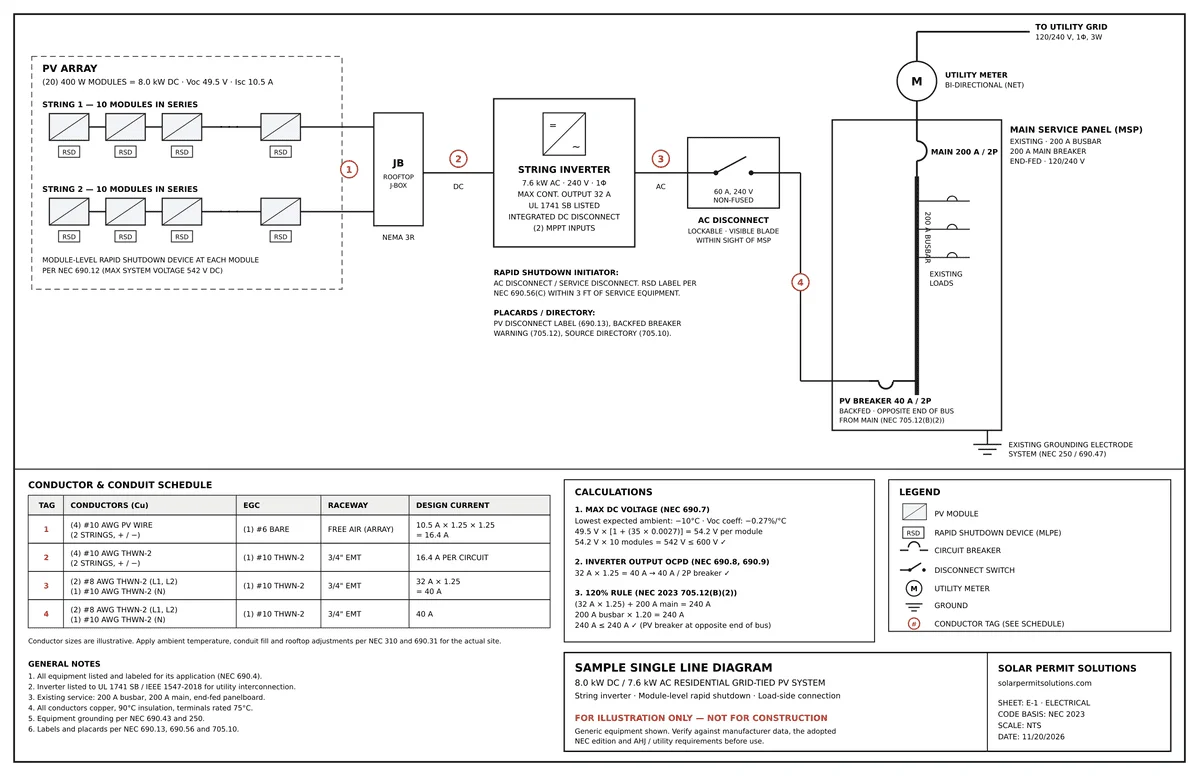
A solar single-line diagram (SLD), also called a PV one-line diagram, is a simplified electrical drawing that shows each circuit of a solar energy system as a single line, from the PV array through the inverter, disconnects, and overcurrent protection to the utility point of interconnection, labeled with the rating of every component. In the US, building departments (AHJs) and utilities review it against the National Electrical Code (NEC) before they approve a permit or interconnection.
The SLD is one of the first drawings a plan reviewer checks in a residential solar permit plan set, and an incomplete one is a common reason permits come back with corrections.
This guide covers what a solar SLD must show for a US permit, the NEC calculations reviewers check, how to draw one for solar-plus-battery systems, and the mistakes we see most often in plan review.
Solar Single Line Diagram: Quick Reference
|
Topic |
What to know |
|---|---|
|
Definition |
A simplified drawing that shows each circuit of a PV system as one line, with the rating of every component |
|
Also called |
One-line diagram, PV one-line, SLD |
|
Who requires it |
Most AHJs (building departments) and utilities, with the permit and interconnection application |
|
What it must show |
Modules and strings, rapid shutdown, inverter, disconnects, conductors, overcurrent protection, main service panel, and interconnection method |
|
Where most SLDs fail |
The interconnection, usually because the NEC 705.12 “120% rule” calculation is missing or does not pass |
|
Battery systems |
Add coupling type (AC or DC), backup loads panel, transfer equipment, and energy storage labels |
|
Cost at SPS |
Included in a flat-rate residential plan set, $1,200 for systems up to 20 kW |
What is a solar single-line diagram?
A solar single-line diagram is a schematic that represents a photovoltaic system’s electrical path with a single line per circuit, regardless of how many conductors the circuit actually has. Each component on that path is drawn as a standard symbol and labeled with its make, model, and electrical ratings.
The “single line” convention keeps the drawing readable. A 240 V AC circuit has two hot conductors, a neutral, and a ground, and a DC string has a positive, a negative, and a ground. Drawing every conductor would turn a simple residential system into a crowded schematic. The SLD shows one line and puts the conductor details (count, size, type, conduit) in a note or a conductor schedule.
SLD vs three-line diagram vs wiring diagram vs site plan
These drawings are often confused, and a permit set may need more than one of them. APEC’s training module on 1-line and 3-line electrical diagrams compares the two formats, and HeatSpring’s walkthrough of a utility-scale single-line diagram shows how the same conventions scale up to large plants.
| Drawing | What it shows | Who uses it |
|---|---|---|
| Single-line (one-line) diagram | Each circuit is one line, with ratings for every component. | Plan reviewers, utilities, designers |
| Three-line diagram | Every conductor: L1, L2, neutral, and ground on AC; positive, negative, and ground on DC | Electricians; some AHJs and utilities for commercial projects |
| Wiring diagram | Terminal-by-terminal connections inside equipment | Installers |
| Site plan / roof layout | Physical location of the array, equipment, and access pathways | Plan reviewers, fire departments |
Rule of thumb: the SLD answers “Is this system electrically safe and code-compliant?” The site plan answers “Where is everything?”
Why do AHJs and utilities require a solar SLD?
The SLD is the reviewer’s fastest way to confirm that a system is safe and meets the NEC and the utility’s interconnection requirements. It serves several people over the life of the system:
- Building department plan reviewers check conductor sizing, overcurrent protection, disconnects, rapid shutdown, and the interconnection method against NEC Articles 690 and 705.
- Utilities use it to review interconnection applications: inverter listing, export capacity, metering, and the point of interconnection.
- Inspectors compare what is installed in the field to what is on the drawing. Any mismatch is a failed inspection.
- Installers use it as the electrical plan on site, so the right breaker, wire size, and disconnect go in the first time.
- Firefighters and first responders rely on the matching labels and placards to find disconnects and rapid shutdown initiators.
- Future technicians use it to troubleshoot, add panels or add a battery years later.
Utilities pay particular attention to the inverter. It should be listed to UL 1741 and meet IEEE 1547-2018, the national standard for connecting distributed energy resources to the grid. The overview of IEEE 1547-2018 from NLR (formerly NREL) explains what it requires.
An accurate SLD is not just paperwork. It is the record that ties design, permit, installation, and maintenance together.
Solar Permit Solutions
Skip the Permit Headaches
We design plan sets that pass inspection the first time. Code-compliant, PE-stamped, accepted by AHJs nationwide.
What must a solar SLD show? (Component checklist)
Every component on the electrical path needs a symbol, a label, and its ratings. The table below lists what we include on every permit-ready SLD and the NEC sections reviewers typically check. References are to NEC 2023, and section numbers differ in other editions. For example, the 2026 NEC deleted 690.47(B), and some states, including Texas, have already moved to the 2026 edition. Confirm the edition your AHJ has adopted. NFPA lets you read the code free online, and HeatSpring explains how to access the 2026 NEC.
| SLD section | What to show | Values to state | Typical NEC reference |
|---|---|---|---|
| PV array | Modules, strings, number of strings | Module make/model, wattage, Voc, Isc, modules per string, temperature-corrected maximum voltage | 690.7, 690.8 |
| Rapid shutdown | MLPE or rapid shutdown devices, initiator location | Device make/model, compliance method | 690.12 |
| DC circuits | Conductors, conduit, combiner boxes, fuses | Conductor type and size, conduit type and size, fuse ratings | 690.8, 690.9, 690.31 |
| Inverter | String inverter, hybrid inverter, or microinverter | Make/model, AC output (kW), maximum continuous output current, UL 1741 listing | 690.4 |
| Disconnects | PV system disconnect, AC disconnect, equipment disconnects | Location, amp rating, fused or non-fused | 690.13, 690.15 |
| AC circuits | Conductors from inverter to point of connection | Conductor size and type, OCPD rating | 690.8, 690.9 |
| Point of interconnection | Backfed breaker (load side) or tap (supply side) | Busbar rating, main breaker rating, PV breaker rating, 120% calculation | 705.11, 705.12 |
| Main service panel | Existing panel and main breaker | Bus rating, main OCPD, service voltage | 705.12, 230 |
| Metering | Utility meter, production meter if required | Location, utility requirements | Utility specifications |
| Energy storage (if any) | Battery, hybrid inverter, backup loads panel, transfer equipment | kWh, kW, coupling type, panel rating | 706, 480 |
| Grounding and bonding | Equipment grounding conductors, grounding electrode conductors | Conductor sizes, electrode type | 690.43, 690.47, 250 |
| Labels and placards | Required warning labels, rapid shutdown label, directory | Label wording and location | 690.12(D), 690.31(G), 705.10 |
Related guides for each part of the SLD
- Disconnects: PV disconnect switch guide: NEC sizing, types and installation rules
- Rapid shutdown: Understanding solar rapid shutdown requirements
- Conductors: Types of solar cables: PV wire, USE-2, THHN and THWN
- Grounding: Solar grounding and bonding: how to pass inspection
- Labels: Solar PV labeling requirements under NEC 690
Two calculations reviewers always check.
1. Temperature-corrected string voltage (NEC 690.7). Module open-circuit voltage rises in cold weather, so the SLD must show the maximum system voltage at the site’s lowest expected ambient temperature. Most designers use the ASHRAE extreme annual mean minimum design dry-bulb temperature for the nearest weather station. For one- and two-family dwellings, PV DC circuits are limited to 600 V.
Example: a module with a Voc of 49.5 V and a temperature coefficient of -0.27%/°C, at a site with a lowest expected ambient temperature of -10°C, is 35°C below the 25°C test condition. The correction is 1 + (35 × 0.0027) = 1.0945, so each module reaches about 54.2 V. A 10-module string is about 542 V, which is under 600 V. A 12-module string would be about 650 V and fail.
2. Circuit and overcurrent sizing (NEC 690.8 and 690.9). Inverter output circuits are sized at 125% of the inverter’s maximum continuous output current. An inverter rated at 32 A needs conductors and a breaker rated for at least 40 A (32 × 1.25).
Which symbols are used on a solar SLD?
Many US electrical drawings use symbols based on IEEE 315 (ANSI Y32.2), although IEEE has since inactivated that standard and symbol styles vary between design firms and software. That is why every SLD should include a symbol legend. Reviewers should not have to guess what a symbol means.
| Component | Common representation |
|---|---|
| PV module or string | Rectangle with diagonal line or sun symbol, labeled with module count |
| String inverter | Box labeled “INV” with DC/AC symbol |
| Microinverter / optimizer | Small box at each module, often labeled “MI” or “OPT” |
| Disconnect switch | Line with an open blade |
| Circuit breaker | Semicircle or square break in the line, labeled with amp rating |
| Fuse | Small rectangle or S-curve in the line, labeled with amp rating |
| Meter | Circle with “M” or “kWh.” |
| Battery | Alternating long and short parallel lines |
| Ground | Three horizontal lines of decreasing length |
| Rapid shutdown device | Box labeled “RSD” at the module or array |
How is the interconnection shown? (Load side vs supply side)
The point of interconnection is where the solar system connects to the building’s electrical service, and it is the part of the SLD reviewers scrutinize most. There are two main methods, summarized below. Our guide to supply-side and load-side interconnection covers them in more depth.
Load-side connection and the 120% rule (NEC 705.12)
Most residential systems connect on the load side with a backfed breaker in the main panel. NEC 705.12(B)(2) in the 2023 edition (705.12(B)(3)(2) in the 2020 edition) allows this when 125% of the inverter output current plus the main breaker rating does not exceed 120% of the panel’s busbar rating, and the PV breaker is installed at the opposite end of the bus from the main breaker.
Example: a 200 A busbar with a 200 A main breaker.
- 120% of 200 A = 240 A allowed on the bus
- 240 A – 200 A main = 40 A maximum PV breaker
- 40 A ÷ 1.25 = 32 A maximum inverter output current, or about 7.68 kW at 240 V
Show this calculation on the SLD or in the electrical notes. If the system is larger than the bus allows, the options are a main breaker derate, a panel upgrade, a supply-side connection or a power control system, and the SLD must show whichever one you choose.
For a real-world reference, the SolarAPP+ sample inspection checklist shows how interconnection and rapid shutdown labeling are documented for a residential approval. The sample was written to an earlier NEC edition, so use it for structure rather than section numbers.
Supply-side connection (NEC 705.11)
In the 2023 NEC, 705.11 is titled “Source Connections to a Service.” A supply-side (line-side) tap connects the PV system between the utility meter and the main breaker. It avoids the 120% limit but requires its own disconnect and overcurrent protection, correctly sized tap conductors and, in many areas, utility approval.
The SLD must show the tap location, the disconnect, fuse or breaker ratings and conductor sizes.
How do you draw an SLD for a solar + battery (hybrid) system?
Adding a battery changes the SLD significantly. Reviewers need to see how the battery charges, where backup power goes, and how the system isolates from the grid during an outage. NEC Article 706 (energy storage systems) and Article 480 (batteries) apply in addition to 690 and 705.
If you are still choosing an architecture, see AC vs DC coupled solar batteries. For the full permit picture, see solar battery permit requirements.
AC-coupled vs DC-coupled storage on the SLD
| AC-coupled | DC-coupled | |
|---|---|---|
| How it connects | Battery has its own inverter and connects on the AC side | Battery connects on the DC side of a hybrid inverter shared with the PV |
| Typical use | Adding a battery to an existing solar system | New solar-plus-storage systems |
| What the SLD shows | Two inverters (PV and battery) and how both connect to the panel | One hybrid inverter with PV and battery inputs |
| Interconnection math | Both inverters’ output current count toward the 120% calculation | Hybrid inverter’s maximum output current counts |
What to add for battery and backup systems
- Battery make/model, usable capacity (kWh) and continuous power (kW)
- Battery disconnect and overcurrent protection
- Backup loads panel (sometimes called a critical loads panel) with its rating and the circuits moved into it
- Transfer equipment (automatic transfer switch, gateway or microgrid interconnect device) that isolates the home from the grid during an outage
- Whole-home vs partial backup configuration
- Energy storage system labels and the updated directory
String inverter vs microinverter vs optimizer SLDs
The inverter architecture changes what the SLD needs to show. For background on how inverters work, see the U.S. Department of Energy’s Solar Integration: Inverters and Grid Services Basics.
- String inverter: DC strings run to a central inverter. Show string voltage and current calculations, DC conductors and the rapid shutdown method (usually module-level devices).
- Microinverters: each module has its own inverter, so the circuits from the roof are AC. Show the number of microinverters per branch circuit (within the manufacturer’s limit), branch circuit breakers, the AC combiner panel and the trunk cable. There are no DC string circuits to size, though each module must stay within the microinverter’s input limits.
- Power optimizers: DC optimizers at each module feed a string inverter. Show the optimizer model, string length within the inverter’s limits and the string voltage the inverter regulates.
Why solar SLDs get rejected in plan review (and how to fix them)
These are the issues we see most often. If you have already received a correction notice, our guide on how to respond to solar permit corrections walks through the resubmission.
- The interconnection does not pass the 120% rule, or the calculation is not shown.
Fix: show busbar rating, main breaker, PV breaker and the calculation on the SLD. If it fails, show the derate, upgrade or supply-side tap. - No temperature-corrected string voltage.
Fix: state the site’s design low temperature, the module coefficient and the corrected maximum voltage. - Rapid shutdown method not identified.
Fix: name the rapid shutdown devices, the initiator location and include the required label. - Conductor or breaker sizes do not match the inverter.
Fix: size from the inverter’s maximum continuous output current × 125%, and keep the same numbers on the SLD, conductor schedule and spec sheets. - Main panel ratings missing.
Fix: always state the busbar rating and main breaker rating. Reviewers cannot check the interconnection without them. - Battery coupling or backup panel not drawn.
Fix: show AC or DC coupling, the backup loads panel, transfer equipment and ESS labels. - Equipment on the SLD does not match the spec sheets or site plan.
Fix: do a final cross-check of every make and model across the full plan set. - The SLD was not updated after an equipment change.
Fix: revise and re-stamp (if required) whenever modules, inverters or batteries change, and keep the revision block current.
How to create a solar SLD: software, templates and who should draw it
Software. Professional SLDs are usually drawn in AutoCAD or similar CAD software, or generated from design platforms that build an SLD from the system design. Generated diagrams are a good starting point, but they still need review against the AHJ’s and utility’s specific requirements.
Templates. Templates work for simple, repeat residential systems. They become risky when reused without checking: old equipment models, wrong breaker sizes and outdated code references carried from job to job are common causes of corrections.
Who should draw it. A solar designer familiar with NEC 690, 705 and 706 and with local AHJ requirements. Some jurisdictions and most commercial solar projects require a professional engineer (PE) stamp on the electrical drawings, and requirements vary by state and AHJ. Our guide to structural vs electrical PE stamps explains when each is needed.
Solar SLD checklist before you submit
☐ Every component shown with make, model and ratings
☐ Modules per string and temperature-corrected maximum voltage stated
☐ Rapid shutdown method and initiator location identified
☐ Conductor sizes, types and conduit noted for every circuit
☐ OCPD sized at 125% of continuous current
☐ All disconnects shown with locations and ratings
☐ Main panel busbar and main breaker ratings stated
☐ Interconnection method shown with 120% calculation (or supply-side details)
☐ Battery, backup panel and transfer equipment shown (if applicable)
☐ Grounding and bonding conductors sized
☐ Required labels and placards listed
☐ Symbol legend included
☐ Equipment matches spec sheets and site plan
☐ Revision block and date current
Frequently asked questions
Skip the Permit Headaches
We design plan sets that pass inspection the first time. Code-compliant, PE-stamped, accepted by AHJs nationwide.
Frequently Asked Questions
Yes. "Single line diagram" and "one-line diagram" mean the same thing: a simplified drawing that shows each circuit as one line. US utilities and building departments more often say "one-line," while "SLD" is common in design software and internationally.
A single line diagram shows each circuit as one line with component ratings. A three-line diagram shows every conductor separately, such as L1, L2, neutral and ground. Residential permits usually need only an SLD. Some utilities and commercial projects also require a three-line.
No. An SLD gives a simplified overview of the whole system and its ratings. A wiring diagram shows terminal-level connections inside and between equipment for installers.
It depends on the jurisdiction and project. Many residential AHJs accept SLDs without a stamp, while some states, AHJs and most commercial projects require a PE-stamped electrical drawing. Check the AHJ's submittal requirements before you submit.
Not in the traditional sense. According to the SolarAPP+ technical FAQ, a traditional site plan and single line diagram are not part of the SolarAPP+ submittal. The contractor's longform document details the equipment, circuits, interconnection and code compliance instead, and SolarAPP+ generates a schematic diagram in the inspection checklist from those inputs. Some AHJs and state programs still ask for a one-line to be uploaded or kept on site for the inspector. SolarAPP+ is only available in participating jurisdictions, and systems that do not qualify go through standard plan review with a full SLD.
You can, but the drawing must meet NEC and AHJ requirements, and errors usually mean corrections and delays. Most installers use a professional designer to get a permit-ready SLD approved the first time.
AutoCAD and other CAD tools are standard for permit-ready drawings. Many solar design platforms can also generate an SLD automatically from the system design, which is then reviewed and adjusted for local requirements.
Usually not. The battery, hybrid inverter, backup loads panel and transfer equipment are added to the system's SLD so reviewers see the whole electrical path in one drawing. Check the utility's interconnection requirements in case it asks for additional storage documentation.
At Solar Permit Solutions, the SLD is part of a complete residential permit plan set, priced at a flat $1,200 for systems up to 20 kW (see pricing), with a 2-5 business day turnaround. Commercial projects are quoted based on size and complexity.
Whenever the system changes: new panels, an inverter replacement, a battery addition or a panel upgrade. The SLD on file should always match what is installed.

SPS Editorial Team
Solar Permit Solutions
Solar Permit Solutions provides professional solar permit design services for residential, commercial, and off-grid installations across all 50 states. Our team ensures permit-ready plan sets delivered fast.
Related Articles

Can You Cancel a Solar Panel Contract After Installation? (2026 Legal Guide by State)
Yes, you can cancel a solar contract after installation. Learn about early termi...
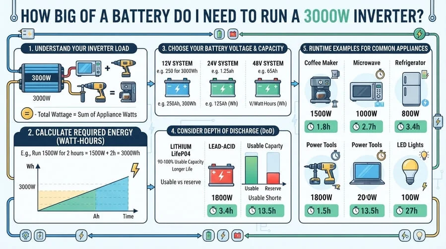
How Big of a Battery Do I Need to Run a 3000W Inverter?
A 3000W inverter needs about 3.3 kWh of usable battery for every hour it runs at...
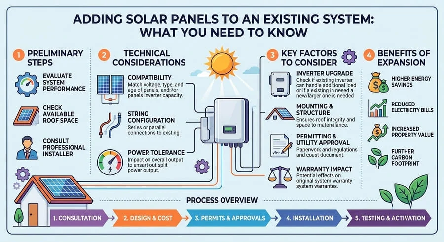
Adding Solar Panels to an Existing System: What You Need to Know
Learn 3 proven methods to expand your solar panel system. Expert guide covers co...