A solar combiner box merges multiple solar string circuits into a single output conductor that feeds the inverter, providing overcurrent protection for each string under NFPA 70 / NEC Article 690. It reduces DC wiring runs, lowers balance-of-system costs, and makes every string independently serviceable – without changing system voltage.
What Does a Solar Combiner Box Do?
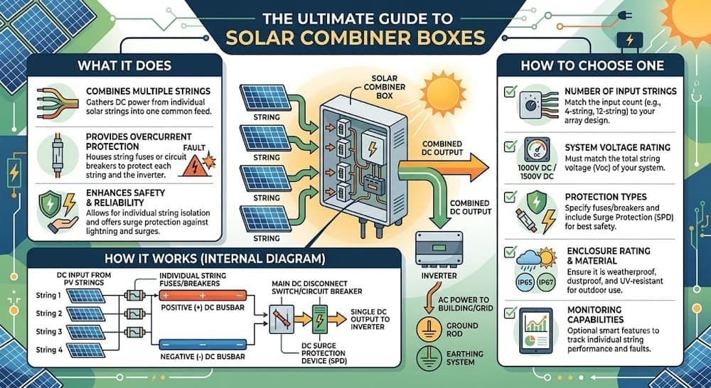
A solar combiner box – also called a photovoltaic combiner box or PV combiner – sits between the solar array and the inverter. Each string of modules terminates on a fused input terminal inside the enclosure. The fused inputs share a common DC bus, so all string currents aggregate onto a single output conductor that runs to the inverter.
In practical terms: instead of running five or ten separate wires from your array to your inverter, the combiner box collects them in one enclosure near the array and sends a single protected output downstream. That reduces wiring labor, shortens DC cable runs, and lets technicians isolate and service any individual string without shutting down the whole array.
How Does a Solar Combiner Box Work?
A photovoltaic combiner box sits in the electrical path between the PV source circuits and the inverter input. Understanding current flow through it clarifies both its protective function and its placement requirements. For circuit sizing behind these steps, see our guide to NEC 690.8 circuit requirements.
Step-by-Step Current Flow
- Solar modules in each string produce DC current at string voltage (typically 300-600 V DC for residential systems; up to 1,500 V DC for utility-scale ground-mount).
- Each string’s positive and negative conductors terminate on separate fuse terminals. Fuses are sized using the NEC 156% rule (Isc x 1.25 x 1.25). DC fault current has no natural zero-crossing, so only DC-rated gPV class fuses – per IEC 60269-6 – can safely interrupt a fault.
- The fused positive conductors land on a common positive busbar; negatives land on a common negative bus. This is the combining point – all string currents aggregate here.
- A DC disconnect switch on the output side isolates the combiner from the inverter for maintenance. See our solar disconnect switch guide for rating requirements.
- The single output conductor pair exits the combiner and runs to the inverter’s DC input terminals, completing the PV output circuit as defined under NEC 690.8.
Does a Solar Combiner Box Increase Voltage?
No. Voltage across each string is determined solely by the number of modules wired in series. When strings of equal voltage are paralleled at the combiner bus, voltage stays constant – only current adds up. A combiner with four 10-amp strings produces roughly 40 amps at the same voltage as a single string. The inverter must be rated for the string voltage; if higher voltage is needed, that is achieved by adding modules in series at the design stage, not at the combiner.
Key Components Inside a PV Combiner Box
Standard units contain the protective basics. Premium models add monitoring and safety features aligned with NEC 2023 changes. For grounding and bonding requirements that interface with the combiner enclosure, see our solar PV grounding and bonding guide.
| Component | Function | Code / Standard Reference |
| String fuses (gPV class) | Interrupt reverse fault current from parallel strings | NEC 690.9(A); IEC 60269-6 |
| Positive and negative busbars | Aggregate parallel string currents into single output | NEC 690.8 |
| DC disconnect switch | Load-break isolation of combiner output circuit | NEC 690.15(C) |
| Surge protective device (SPD) | Clamps lightning-induced transients on DC side | NEC 690.11; UL 1449 |
| Arc-fault circuit interrupter (AFCI) | Detects series arc faults in DC conductors at 80 V+ | NEC 690.11 |
| String-level current sensors | Per-string current telemetry for fault detection | Optional; standard in utility-scale |
| Remote rapid shutdown (RSD) relay | Enables NEC 690.12 compliance from combiner location | NEC 690.12 |
Solar Permit Solutions
Need Solar Permit Plans?
Professional, permit-ready solar plan sets delivered fast. Residential and commercial projects across all 50 states.
Is a Solar Combiner Box Necessary?
Not always for small residential systems – but effectively always for four or more strings.
When You Do Not Need One
If a system has two or three strings and the inverter’s input terminals can accept them directly, a separate combiner box may not be required. Microinverter and DC-optimized string inverter designs (such as SolarEdge with its built-in string combiner) often eliminate the need for an external box. Verify your inverter’s documentation: does it integrate fused input combiners internally?
When a Combiner Box Is Required or Strongly Advised
- Four or more strings in parallel – NEC 690.9(A) triggers individual per-string overcurrent protection requirements whenever three or more strings are paralleled and fault current could exceed module or conductor ratings.
- Central inverter designs – central inverters for 30-100+ strings require one or more combiners to aggregate source circuits. These are called string combiners or array combiners.
- Long source circuit runs – a combiner near the array shortens individual source-circuit runs and reduces DC Balance-of-System costs significantly.
- Ground-mount and utility-scale projects – distributed combiner boxes positioned within the array plane minimize resistive losses and allow string-level fault isolation.
- Fuse servicing safety – any system where fuse replacement could expose live DC conductors requires a disconnecting means near the fuse per NEC 690.15. See our detailed NEC 690.16 fuse servicing guide for how this requirement evolved and currently applies.
A failed combiner box can produce arc flash events with visible flames and smoke. OSHA identifies arc flash as a primary solar installation hazard. All combiner boxes installed in U.S. systems must carry an NRTL listing – most commonly to UL 1741 or applicable product standards such as UL 508A.
Where to Install a Solar Combiner Box
The combiner box belongs between the solar array and the inverter – ideally at or near the array. Its location is shown on the solar single-line diagram and reviewed by the AHJ during plan check.
Optimal placement: centered within the array to equalize source circuit conductor lengths. Unequal conductor lengths create minor current imbalances between strings and add resistive losses.
Avoid locating the combiner in a remote equipment room. This forces long individual source-circuit runs, increases DC BOS costs, and adds resistive losses that compound across large arrays.
Enclosure rating: outdoor installations require NEMA 4X (corrosion-resistant, IP66 equivalent). Covered outdoor locations such as under eaves allow NEMA 3R. Dry indoor locations require NEMA 1 minimum.
How to Choose the Right Solar Combiner Box
Match the following seven parameters to your system design before specifying equipment. Selecting the wrong combiner is a common source of permit rejections. For the full plan-set context, see our guide to solar permit design and plan sets.
1. String Count and Input Fuse Slots
Count the number of strings terminating at the combiner. Standard residential models offer 4-12 fuse inputs; commercial models scale from 12-24 inputs; utility-scale combiners accommodate far more. Build in at least 10-15% spare capacity for expansion.
2. System Voltage Class
- 600 V DC – residential one- and two-family dwellings. See our NEC 690.7 voltage limits guide for calculation methods. All DC-side equipment must be rated for the full maximum system voltage.
- 1,000 V DC – commercial and multi-family building-mounted systems. Combiner box fuses, busbars, and disconnects must all be rated for 1,000 V DC minimum.
- 1,500 V DC – utility-scale ground-mount only per NEC 690.31(G), using 2,000 V-rated conductors. Prohibited inside buildings with habitable spaces.
3. Fuse Ampere Rating
The NEC 156% rule per NEC 690.8(A)-(B): multiply module Isc by 1.25 (maximum circuit current), then multiply again by 1.25 (conductor ampacity) = Isc x 1.5625. Round up to the next standard fuse size. Verify the selected rating does not exceed the module’s maximum series fuse rating on its datasheet.
Example: Module Isc = 10.5 A. Step 1: 10.5 x 1.25 = 13.125 A. Step 2: 13.125 x 1.25 = 16.4 A. Select the next standard size: a 20 A fuse. Confirm 20 A does not exceed the module’s max series fuse rating.
Use only DC-rated gPV class fuses per IEC 60269-6:2010+AMD1:2021. Never substitute AC fuses – they cannot safely interrupt DC fault current, which has no natural zero-crossing.
4. DC Disconnect Type and Location
NEC 690.15(C) requires a load-break rated disconnect in the combiner or within 6 feet of it for any rooftop-mounted combiner. See our NEC 690.15 disconnecting means guide for full requirements. Rate the disconnect for the combined array short-circuit current and maximum system voltage – not merely nominal operating current.
5. Built-in Protection Features
- AFCI: required by NEC 690.11 for any PV system with DC circuits at 80 V or higher – covering virtually all string inverter systems. See our solar panel safety codes guide for how AFCI, GFCI, and rapid shutdown work together. Verify whether AFCI is integrated into the combiner, the inverter, or a standalone device.
- SPD: a Type 1 surge protective device on the DC combiner input is standard practice for exposed roof and ground-mount systems. SPD requirements appear in NEC 690.11.
- Monitoring: string-level current monitoring is not code-required for most systems but is standard in commercial and utility-scale builds. It significantly shortens fault diagnosis time.
6. Certification and Listing
All combiner boxes must carry an NRTL listing. Most manufacturers certify as balance-of-system equipment to UL 1741 or UL 508A (industrial control panels). See UL’s PV inverter and BOS certification page for the full scope of applicable product standards. Do not install unlisted equipment regardless of price.
7. NEC Edition in Your Jurisdiction
Combiner box documentation in permit sets must reference the NEC edition the local AHJ enforces. See our NEC 2023 Article 690 updates guide for the current cycle changes affecting AFCI, disconnects, and wiring methods. See also NFPA 70 code development to verify the current adopted cycle.

Solar Combiner Boxes in Permit Plan Sets and AHJ Reviews
Missing or incorrect combiner box specifications are a common cause of plan check corrections. NREL research on permitting timelines confirms that complete, accurate documentation is the single biggest driver of permit approval speed. See our solar engineering requirements guide for AHJ documentation standards.
A PE-stamped, AHJ-ready permit plan set for a system with a combiner box must include the following:
- Single-line diagram showing combiner box location between PV source circuits and inverter.
- String count, fuse ampere rating, fuse voltage rating, and fuse class (gPV).
- Combiner output conductor gauge and conduit method.
- DC disconnect rating (voltage and current) and location confirming NEC 690.15(C) compliance.
- Combiner box manufacturer, model number, and NRTL listing number.
- AFCI and SPD callouts if integrated.
- Required solar PV labeling per NEC 690.56.
- Fuse servicing disconnect access note referencing current NEC 690.15 requirements.
Solar Permit Solutions produces PE-stamped plan sets that include full combiner box documentation for residential and commercial systems in all 50 states. Learn more about our solar permit design services.
Combiner Box Applications: Residential, Commercial, and Utility-Scale
| System Type | Typical String Count | Combiner Type | Voltage Class | Key Considerations |
| Residential rooftop | 2-12 | 4-12 input string combiner or integrated inverter input | 600 V DC max | Often omitted for 3 or fewer strings, microinverters eliminate need entirely |
| Commercial rooftop | 10-50 | Multi-input string combiner (12-24 inputs) | 1,000 V DC max | AFCI required (NEC 690.11); NEMA 4X enclosure required outdoors |
| Ground-mount utility-scale | 50-4,000+ | Array combiner / recombiner architecture | 1,500 V DC max | Multiple combiner tiers; full PE stamp required on permit set |
| Off-grid / battery backup | 2-10 | Small combiner or direct string input | 48-600 V DC | Battery BMS coordination required; NEC Article 706 may apply |
Solar Combiner Box Maintenance and Safety
Combiner boxes require periodic inspection – especially after severe weather, in coastal environments, and before any DC-side service work. See OSHA’s solar electrical safety guidance for lockout/tagout and arc-flash PPE requirements that apply to combiner box servicing.
Critical safety note: PV modules continue producing voltage even when the inverter is off. Shutting down the inverter does not de-energize the combiner. Always use the DC disconnect to isolate the output circuit before opening the enclosure. Work with arc-flash PPE rated for the DC system voltage. The NREL solar safety research hub and OSHA both identify DC arc flash as a primary hazard during combiner box service.
Inspect combiner boxes periodically for:
- Moisture ingress or condensation inside the enclosure.
- Loose or corroded fuse terminals.
- Blown fuses indicating a string-level fault requiring investigation before replacement.
- Damaged or discolored wiring indicating overheating.
- SPD status indicators (if present) – replace SPDs that show fault indication.
Frequently Asked Questions
Need Solar Permit Plans?
Professional, permit-ready solar plan sets delivered fast. Residential and commercial projects across all 50 states.
Frequently Asked Questions
A solar combiner box collects the DC output of multiple solar string circuits and combines them into a single output conductor that runs to the inverter. Each string terminates on a fused input terminal that prevents reverse fault currents from damaging modules. The output side feeds the inverter through a load-break DC disconnect switch.
No. Voltage is fixed by the number of modules in series within each string. Paralleling strings at the combiner bus adds current, not voltage. The combined output voltage equals the individual string voltage.
For systems with two to three strings where the inverter accepts direct string inputs, a separate combiner box is typically not required. NEC 690.9(A) triggers per-string overcurrent protection requirements when three or more strings are paralleled and fault current could exceed equipment ratings. For four or more strings, and for any central inverter design, a combiner box is effectively required.
A PV junction box is a simple pass-through enclosure for conductor splices with no overcurrent protection. A PV combiner box actively aggregates multiple circuits, provides individual string fuses, and typically incorporates a DC disconnect switch. The terms are sometimes used interchangeably in the field, but they are functionally distinct components.
Size fuses to at least 156% of the module's short-circuit current (Isc x 1.25 x 1.25) per NEC 690.8. Round up to the next standard fuse size and verify the rating does not exceed the module's maximum series fuse rating. Use only DC-rated gPV class fuses – never substitute AC fuses, which cannot safely interrupt DC fault current.
No. DC fault current has no natural zero-crossing, making arc interruption far more difficult than in AC circuits. AC-rated overcurrent devices are not listed for DC PV applications and will not safely interrupt a DC short-circuit. Always specify gPV-class fuses or DC-rated circuit breakers listed for PV use at the system voltage class.
A string combiner collects individual source circuits (one fuse per string) and outputs to an inverter or to a higher-level combiner. An array combiner (also called a recombiner) collects the outputs of multiple string combiners. Utility-scale projects typically use both in a tiered architecture to minimize DC cable runs across large array fields.
NEC 690.15(C) requires a load-break rated disconnecting means located in the combiner box or within 6 feet of it for any combiner mounted on a rooftop of a dwelling or other building. This allows first responders and service technicians to de-energize the combiner output quickly and safely. Ground-mount combiners located away from buildings may use non-load-break isolators if a main load-break disconnect is provided elsewhere in the system.
SPS Editorial Team
Solar Permit Solutions
Solar Permit Solutions provides professional solar permit design services for residential, commercial, and off-grid installations across all 50 states. Our team ensures permit-ready plan sets delivered fast.
Related Articles

Utility Interconnection Requirements for Solar Installers: The 6 Rules Every Utility Enforces
interconnection agreement, UL 1741 and IEEE 1547 certified inverters, a utility-...

How to Respond to Solar Permit Corrections (And Get Approved on Resubmission)
To respond to a solar permit correction, read every comment from every reviewing...

Can an EV Charging Station Be Powered by Solar? Here’s How to Build One
Yes, an EV charging station can be powered by solar. A grid-tied solar array pai...